
Wiring Diagram – Configuration Diagrams
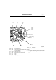

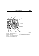
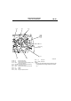
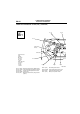


ENGINE AND TRANSMISSION
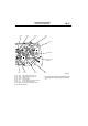
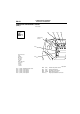
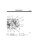
CONFIGURATION DIAGRAMS
80-17
NOTE: .
• On A/T only, the standard routing positions for the
corrugated tube and wiring harness are marked
by*.
AC301133
AC
9
10
11
13
B-103
B-104
B-105
B-107
B-108
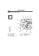
Battery wiring
harness
B-109
B-110
B-111
*
B-112
B-118
B-111 (2-B) Water temperature sensor unit
B-112 (1-B) Water temperature gauge unit
B-113 (3-GR) Ignition coil 2
B-114 (1-B) A/C compressor
B-115 (1) Power steering fluid pressure switch
B-116 (3-B) Engine crank angle sensor
B-117 (2-GR) Engine control detonation sensor
B-118 (28-GR) ABS-ECU