
Wiring Diagram – Configuration Diagrams
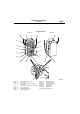
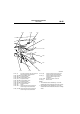
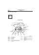
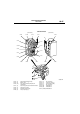
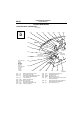
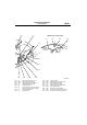
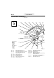

DASH PANEL
CONFIGURATION DIAGRAMS
80-35
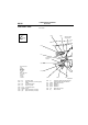
NOTE: .
1. The connector colour marked by
*1
is for the
female side.For the male side, the colour is grey.
2. The connector colour marked by
*2
is for the
female side.For the male side, the colour is milky
white.
AC301148
AB
5
14
15
C-103
C-102
C-101
C-139
C-138
C-137
C-140
C-136
C-135
C-134
C-121 (3) Front wiring harness (LH) and instrument
panel wiring harness combination
C-122 (35-GR) Engine-A/T-ECU <A/T>
C-123 (26-Y) Engine-ECU <M/T>
C-124 (26-GR) Engine-A/T-ECU <A/T>
C-125 (16-Y) Engine-ECU <M/T>
C-126 (28-GR) Engine-A/T-ECU <A/T>
C-127 (12-Y) Engine-ECU <M/T>
C-128 (30-GR) Engine-A/T-ECU <A/T>
C-129 (22-Y) Engine-ECU <M/T>
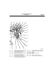
C-134 (33) J/C (6)
C-135 (22-L) Instrument panel wiring harness and
control wiring harness combination
C-136 (10-GR) Instrument panel wiring harness and
control wiring harness combination
C-137 (25) Instrument panel wiring harness and
control wiring harness combination
C-138 (3) Instrument panel wiring harness and
Instrument panel wiring harness
combination
C-139 (12-B) A/C-ECU or heater control unit
C-140 (6) Blower switch