
Wiring Circuit Diagrams

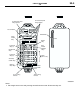

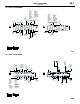


CENTRALIZED JUNCTION
CIRCUIT DIAGRAMS
90-10
CENTRALIZED JUNCTION
M1901000300991
FUSIBLE LINK AND FUSE
ENGINE COMPARTMENT
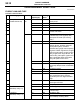
No. Power supply circuit Name Rated
capacity (A)
Housing
colour
Load circuit
1 Battery/ Alternator
(Fusible link No.26)
Fusible
link
60 Yellow Fuse No.15, 16, 19, 20 (in junction
block) circuit
2 50 Red Fan controller
3 60 Yellow ABS-ECU
4 40 Green Ignition switch circuit
5 30 Pink Power window main switch and power
window sub switch
6 Fuse 15 Blue Front fog lamp, front fog lamp
indicator lamp, front fog lamp relay
and spare connector (for front fog
lamp)
7 10 Red Horn relay and horn
8 20 Yellow Air cleaner air flow sensor, camshaft
position sensor, emission solenoid
valve (EGR system), emission
solenoid valve (purge control system),
engine-A/T-ECU, engine-ECU, engine
control oxygen sensor, engine control
relay, engine crank angle sensor, fan
control relay, fuel injector, ignition coil
relay, immobilizer-ECU and throttle
body idle speed control servo
9 10 Red A/C compressor
10 15 Blue ABS-ECU, engine-A/T-ECU, high
mount stop lamp and rear combination
lamp
11 15 Blue Accessory socket
12 7.5 Brown Alternator
13 10 Red ETACS-ECU, front turn signal lamp,
rear combination lamp, side turn
signal lamp and turn signal indicator
lamp
14 20 Yellow A/T control solenoid valve assembly
and engine-A/T-ECU
15 15 Blue Fuel pump
16 Front-ECU
(Headlamp relay: HI)
10 Red Headlamp (RH)
17 10 Red Headlamp (LH) and high beam
indicator lamp
18 Front-ECU
(Headlamp relay: LO)
10 Red Headlamp (RH)
19 10 Red Headlamp (LH), headlamp assembly
and headlamp levelling switch