
Wiring Diagram – Configuration Diagrams
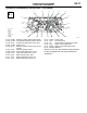
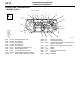
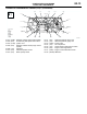
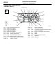
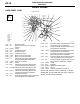
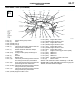
Table Of Contents
DASH PANEL
CONFIGURATION DIAGRAMS
80-17
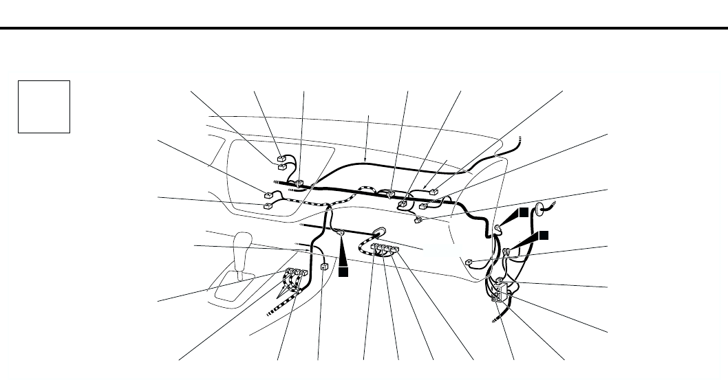
DASH PANEL <LHD> (CONTINUED)
NOTE: The connector colour marked by
*
is for the
female side.For the male side, the colour is grey for
Sedan, and milk white for Wagon.
AC301143
C-140
C-102
C-103
C-101
C-132
C-139
C-130
Y
4
Connector
symbol
-101
thru
-140
C
Connector colour
code
B : Black
BR : Brown
G : Green
GR : Gray
L : Blue
None : Milk white
O : Orange
R : Red
V : Violet
Y : Yellow
Instrument panel
wiring harness
C-131
C-133
AB
C-104 C-106 C-107
C-109
C-110
C-112
C-114
C-116
C-119
C-126
C-127
C-128
C-129
2
C-108
C-124
C-125
C-122
C-123
3
Control wiring
harness
A/C wiring
harness
Antenna
feeder
cable
C-101 (4) Hazard warning lamp switch
C-102 (4) Clock
C-103 (22-GR) J/C (1)
C-104 (22-GR) J/C (3)
C-106 (7) Instrument panel wiring harness and A/C
wiring harness combination
C-107 (7) Outside /Inside air selection damper
control motor
C-108 (2-R) Air bag module (squib) <Passenger’s
side>
C-109 (4) Resistor
C-110 (2) Blower motor
C-112 (16) Instrument panel wiring harness and front
door wiring harness (RH) combination
C-114 (25) Front wiring harness (RH) and instrument
panel wiring harness combination
C-116
(9-GR
*
)
Instrument panel wiring harness and floor
wiring harness (RH) combination
C-119 (13) Instrument panel wiring harness and floor
wiring harness (RH) combination
C-122 (35-GR) Engine-A/T-ECU <A/T>
C-123 (26-Y) Engine-ECU <M/T>
C-124 (26-GR) Engine-A/T-ECU <A/T>
C-125 (16-Y) Engine-ECU <M/T>
C-126 (28-GR) Engine-A/T-ECU <A/T>
C-127 (12-Y) Engine-ECU <M/T>
C-128 (30-GR) Engine-A/T-ECU <A/T>
C-129 (22-Y) Engine-ECU <M/T>
C-130 (4) Engine control oxygen sensor (Rear)
C-131 (20-Y) SRS-ECU
C-132 (28-Y) SRS-ECU
C-133 (20-Y) SRS-ECU
C-139 (16-B) A/C-ECU or heater control unit
C-140 (6) Blower switch