
Wiring Diagram – Configuration Diagrams
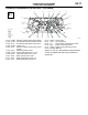
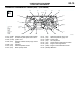
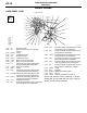
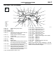
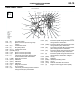
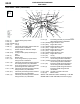
Table Of Contents
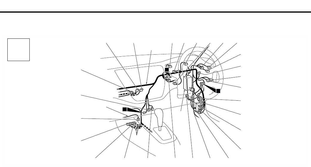
DASH PANEL
CONFIGURATION DIAGRAMS
80-19
DASH PANEL <RHD>
M1801000601051
AC301149
C-10
C-09 C-08
Control wiring
harness
C-37
C-16
C-17 C-18
C-11
C-19
Y
4
Connector
symbol
-01
thru
-37
C
Connector colour
code
B : Black
BR : Brown
G : Green
GR : Gray
L : Blue
None : Milk white
O : Orange
R : Red
V : Violet
Y : Yellow
Instrument panel
wiring harness
AB
C-04 C-07 C-06 C-05 C-02 C-01
J/B
C-34
C-33
C-31
C-30
C-28
C-26
C-23
C-24C-20
C-32
C-35
2
C-36
6
C-01 (6) Fog lamp switch
C-02 (1) Spare connector (for front fog lamp
switch)
C-04 (21) Combination meter
C-05 (4) Stop lamp switch
C-06 (21-L) Combination meter
C-07 (22-GR) J/C (3)
C-08 (1-B) Spare connector (for audio)
C-09 (14) Spare connector (for audio)
C-10 (1) Instrument panel wiring harness and
antenna feeder cable combination
C-11 (16-B) Diagnosis connector
C-16 (20-Y) SRS-ECU
C-17 (28-Y) SRS-ECU
C-18 (20-Y) SRS-ECU
C-19 (12) Diagnosis connector
C-20 (2) No connection
C-23 (13) Instrument panel wiring harness and floor
wiring harness (RH) combination
C-24 (6-L) Instrument panel wiring harness and roof
wiring harness combination
C-26 (9-GR) Instrument panel wiring harness and floor
wiring harness (RH) combination
C-28 (25) Front wiring harness (RH) and instrument
panel wiring harness combination
C-30 (20) Instrument panel wiring harness and front
door wiring harness (RH) combination
C-31 (6) Instrument panel wiring harness and roof
wiring harness combination <Wagon>
C-32 (22-B) J/C (4)
C-33 (6-L) Rheostat
C-34 (6-GR) Headlamp levelling switch
C-35 (22-L) J/C (2)
C-36 (11-B) Remote controlled mirror switch
C-37 (4) Engine control oxygen sensor (Rear)