
Wiring Diagram – Configuration Diagrams
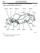
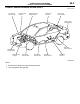
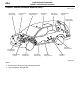
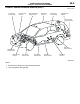
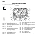
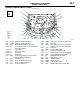
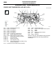
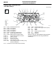
Table Of Contents
ENGINE AND TRANSMISSION
CONFIGURATION DIAGRAMS
80-9
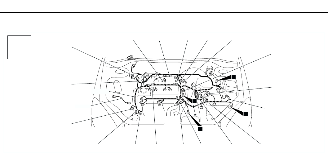
ENGINE AND TRANSMISSION <4G1-MPI (LHD) > (CONTINUED)
NOTE: On A/T only, the standard routing positions
for the corrugated tube and wiring harness are
marked by*.
AC301128
B-118
B-101 B-102
B-113
B-114
B-115
B-116
B-117
Earth cable
Control wiring
harness
Connector colour
code
B : Black
BR : Brown
G : Green
GR : Gray
L : Blue
None : Milk white
O : Orange
R : Red
V : Violet
Y : Yellow
Connector
symbol
-101
thru
-118
B
*
AC
9
10
11
13
B-103
B-104
B-105
B-107
B-108
Battery wiring
harness
B-109
B-110
B-111
*
B-112
B-101 (2-BR) Emission solenoid valve (EGR system)
B-102 (4-GR) Inlet manifold absolute pressure sensor
B-103 (6-B) Throttle body idle speed control servo
B-104 (3-GR) Ignition coil 1
B-105 (2-B) Emission solenoid valve (Purge control
system)
B-107 (3-B) Camshaft position sensor
B-108 (3-GR) Output shaft speed sensor <A/T>
B-109 (3-B) Input shaft speed sensor <A/T>
B-110 (2-B) Back-up lamp switch <M/T>
B-111 (2-B) Water temperature sensor unit
B-112 (1-B) Water temperature gauge unit
B-113 (3-GR) Ignition coil 2
B-114 (1-B) A/C compressor
B-115 (1) Power steering fluid pressure switch
B-116 (3-B) Engine crank angle sensor
B-117 (2-GR) Engine control detonation sensor
B-118 (28-GR) ABS-ECU