
Wiring Diagram – Configuration Diagrams

ENGINE AND TRANSMISSION
CONFIGURATION DIAGRAMS
80-14
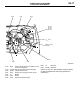
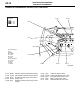
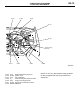
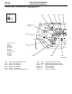
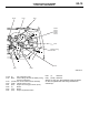
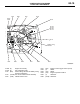
ENGINE AND TRANSMISSION <4G1-MPI (RHD)>
M1801000401950
AC301132
AD
B-02
B-03
B-04 B-05
B-22
B-23
B-24
B-25
B-26
Control wiring
harness
B-09
Connector colour
code
B : Black
BR : Brown
G : Green
GR : Grey
L : Blue
None : Milk white
O : Orange
R : Red
V : Violet
Y : Yellow
*
Connector
symbol
-01
thru
-26
B
Earth cable
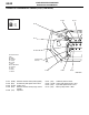
B-01 (5-GR) Windshield wiper motor
B-02 (2-GR) Fuel injector 1
B-03 (2-GR) Fuel injector 2
B-04 (2-GR) Fuel injector 3
B-05 (2-GR) Fuel injector 4
B-06 (3-GR) Throttle body throttle sensor
B-07 (3-B) Vehicle speed sensor <M/T>
B-09 (2-GR) Brake fluid level indicator switch
B-10X (1) Engine speed detection connector
B-14X (4) Ignition coil relay
B-15X (4) A/T control relay
B-16X (4) Engine control relay