
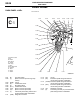
Wiring Diagram – Configuration Diagrams


AC502054
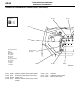
C-142
AB
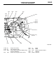
C-104
C-106
C-143
C-107
C-109
C-149
C-110
C-144
C-112
C-114
C-116
C-119
C-126
C-127
C-128
C-129
2
C-108
C-124
C-125
C-122
C-123
3
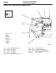
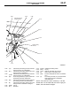
Control wiring
harness
A/C wiring
harness
Antenna
feeder
cable
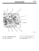
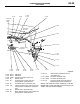
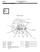
C-132 (28-Y) SRS-ECU
C-133 (20-Y) SRS-ECU
C-139 (16-B) A/C-ECU or heater control unit
C-140 (6) Blower switch
C-141 (6) Air mixing door control motor and
potentiometer <Automatic A/C>
C-142 (2) Air thermo sensor <Automatic A/C>
C-143 (13) Instrument panel wiring harness and A/C
wiring harness combination <Automatic
A/C>
C-144 (6) Blower motor <Automatic A/C>
C-145 (6) Mode selection damper control motor and
potentiometer <Automatic A/C>
C-146 (2) Heater water temperature sensor
<Automatic A/C>
C-147 (20-B) A/C-ECU <Automatic A/C>
C-148 (16-B) A/C-ECU <Automatic A/C>
C-149 (2) Instrument panel wiring harness and
tweeter wiring harness combination
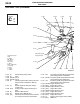
DASH PANEL
CONFIGURATION DIAGRAMS
80-29
NOTE: The connector colour marked by
*
is for the
female side.For the male side, the colour is grey for
Sedan, and milk white for Wagon.