
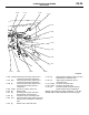
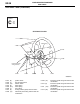
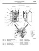
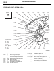
Wiring Diagram – Configuration Diagrams

AC502058
AB
5
14
15
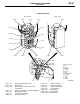
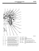
C-103
C-102
C-101
C-148
C-147
C-138
C-146
C-137
C-140
C-139
C-136
C-135
C-134
C-145
C-141
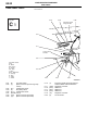
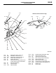
C-136 (10-GR) Instrument panel wiring harness and
control wiring harness combination
C-137 (25) Instrument panel wiring harness and
control wiring harness combination
C-138 (3) Instrument panel wiring harness and
Instrument panel wiring harness
combination
C-139 (12-B) A/C-ECU or heater control unit
C-140 (6) Blower switch
C-141 (6) Air mixing door control motor and
potentiometer <Automatic A/C>
C-142 (2) Air thermo sensor <Automatic A/C>
C-143 (13) Instrument panel wiring harness and A/C
wiring harness combination <Automatic
A/C>
C-144 (6) Blower motor <Automatic A/C>
C-145 (6) Mode selection damper control motor and
potentiometer <Automatic A/C>
C-146 (2) Heater water temperature sensor
<Automatic A/C>
C-147 (20-B) A/C-ECU <Automatic A/C>
C-148 (16-B) A/C-ECU <Automatic A/C>
C-149 (2) Instrument panel wiring harness and
tweeter wiring harness combination
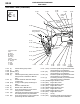
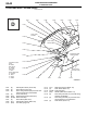
DASH PANEL
CONFIGURATION DIAGRAMS
80-35
NOTE: The connector colour marked by
*
is for the
female side.For the male side, the colour is grey.