
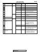
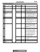
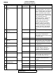
Wiring Circuit Diagrams
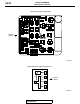
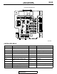
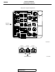
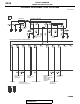
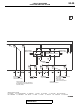
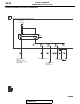

CENTRALIZED JUNCTION
TSB Revision
CIRCUIT DIAGRAMS
90-24
12 ETACS-ECU (IG1
relay)
Fuse 7.5 Brown A/C-ECU <Vehicles with air
conditioning system>, A/C control
panel <Vehicles with air conditioning
system>, center panel unit, column
switch, combination meter, heater
control module <Vehicles without air
conditioning system>, heater control
panel <Vehicles without air
conditioning system>, heated seat
relay, KOS-ECU, rear window
defogger relay, receiver antenna
module <Vehicles with KOS>,
AWC-ECU, shift lever <TC-SST>,
SRS-ECU, steering wheel sensor,
sunroof motor assembly, transaxle
assembly <TC-SST> and wireless
control module <Vehicles without
KOS>
13 ETACS-ECU (ACC
relay 2)
15 Blue Accessory socket and cigarette lighter
14 Fusible link No.34 10 Red Fuel pump relay 2, IG1 relay, power
window relay in ETACS-ECU,
ETACS-ECU, engine control module
and injector relay
15 20 Yellow Sunroof motor assembly
16 ETACS-ECU (ACC
relay 2)
10 Red CAN box unit, multivision display,
radio/CD player, door mirror assembly
(LH, RH) and shift lever <TC-SST>
17 Fusible link No.34 10 Red ASC-ECU, front seat assembly (LH)
and AWC-ECU
18 ETACS-ECU (IG1
relay)
7.5 Brown Backup light (LH, RH), ETACS-ECU,
multivision display, shift lever
<TC-SST>, spare connector (for
navigation unit) and SRS-ECU
19 Fusible link No.37 15 Blue
−
20 Fusible link No.34 Fusible
link
30 Pink Front power window sub switch,
power window main switch and rear
power window motor (LH, RH)
21 Fusible link No.37 30 Pink Fuse No.22 in passenger
compartment and rear window
defogger
22 Rear window
defogger relay
Fuse 7.5 Brown Door mirror assembly
23 Fusible link No.34
− − −
24
− − −
25 30 Green Heated seat assembly (LH, RH) and
heated seat switch
No. Power supply circuit Name Rated
capacity (A)
Housing
color
Load circuit