
Wiring Diagram – Configuration Diagrams
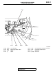
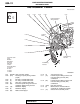

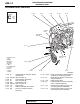

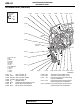


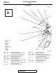

INSTRUMENT PANEL
TSB Revision
CONFIGURATION DIAGRAMS
80A-15
ACD03457
C-106
AC
C-109
C-131C-102
Instrument panel
wiring harness
Floor wiring
harness
C-123
C-121
C-122
C-105
C-115
C-117
C-116
3
2
C-132
C-118
Y
C-120
C-112
C-113
C-119 (5-G) Air mixing damper control motor and
potentiometer
C-120 (2) Fin thermo sensor <Vehicles with air
conditioning system>
C-121 (4) Heater resister <Vehicles without
automatic air conditioning system>
C-122 (4) Power transistor <Vehicles with
automatic air conditioning system>
C-123 (2) Blower motor
C-124 (22) Instrument panel wiring harness and
floor wiring harness combination
C-125 (12-GR) Joint connector (6) and floor wiring
harness combination
C-126 (12-GR) Joint connector (6) and instrument
panel wiring harness combination
C-129 (5) ASC off switch
C-131 (32) KOS and OSS-ECU
C-132 (16) KOS and OSS-ECU