1A-0-1 ENGINE 4G6 SERIES CONTENTS GENERAL INFORMATION . . . . . . . . . . . . . . . . . . . . . . . . . . . . . . . . . . . . . . . . . . . . 11A-0-3 1. SPECIFICATIONS . . . . . . . . . . . . . . . . . . . . . . . . . . . . . . . . . . . . . . . . . . . . . . . . 11A-1-1 SERVICE SPECIFICATIONS . . . . . . . . . . . . . . . . . . . . . . . . . . . . . . . . . . . . 11A-1-1 TORQUE SPECIFICATIONS . . . . . . . . . . . . . . . . . . . . . . . . . . . . . . . . . . . . .
11A-0-2 NOTES E Mitsubishi Motors Corporation Dec.
4G6 ENGINE - General Information 11A-0-3 GENERAL INFORMATION SOHC-4G63 Descriptions Specifications Type In-line OHV, SOHC Number of cylinders 4 Combustion chamber Pentroof type Total displacement dm3 1,997 Cylinder bore mm 85.0 Piston stroke mm 88.
11A-0-4 4G6 ENGINE - General Information GDIt Descriptions Specifications Type In-line OHV, SOHC Number of cylinders 4 Combustion chamber Pentroof + curved top piston type Total displacement dm3 2,351 Cylinder bore mm 86.5 Piston stroke mm 100.0 Compression ratio 11.
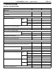
11A-1-1 4G6 ENGINE - Specifications 1. SPECIFICATIONS SERVICE SPECIFICATIONS Items Standard value Limit Auto-tensioner rod projection length mm 12 - Auto-tensioner rod pushed-in amount [when pushed with a force of 98 - 196 N] mm 1.0 or less - Timing belt Rocker arms and camshaft 4G63 SOHC Intake 37.39 36.89 Exhaust 37.14 36.64 4G64 SOHC Intake 37.39 36.89 Exhaust 36.83 36.33 Lash adjuster leak down time [diesel fuel at 15 - 20_C] seconds/mm 3 - 20/1.
11A-1-2 4G6 ENGINE - Specifications Items Standard value Limit Intake 0.02 - 0.05 0.10 Exhaust 0.03 - 0.07 0.15 Intake 0.02 - 0.05 0.10 Exhaust 0.05 - 0.09 0.15 45_ - 45.5_ - SOHC 51.0 50.0 GDI 48.3 47.3 SOHC 267/44.2 - GDI 294/40.0 - SOHC 2_ or less Maximum 4_ GDI 1.5_ or less Maximum 4_ 0.9 - 1.3 - SOHC 6.0 - GDI 6.6 - Valve guide projection from cylinder head upper surface mm SOHC 14.0 - GDI 19.5 - Valve stem projection mm SOHC 49.30 49.
11A-1-3 4G6 ENGINE - Specifications Items Standard value Limit Drive gear 0.08 - 0.14 - Driven gear 0.06 - 0.12 - 78 or more - 4G63 85.0 - 4G64 86.5 - No. 1 0.02 - 0.06 0.1 No. 2 0.02 - 0.06 0.1 No. 1 0.25 - 0.35 0.8 No. 2 0.40 - 0.55 0.8 Oil ring side rail 0.10 - 0.40 1.0 Piston pin outer diameter mm 22.0 - Piston pin press-in load N (Room temperature) 7,350 - 17,200 - Crankshaft pin oil clearance mm 0.02 - 0.05 0.
11A-1-4 4G6 ENGINE - Specifications TORQUE SPECIFICATIONS Items Nm Alternator and ignition system Water pump pulley 9 Adjusting bolt 10 Lock bolt 22 Alternator brace 23 Alternator pivot nut 44 Crankshaft pulley 25 Ignition coil (Multipoint fuel injection) 10 Spark plug 25 Distributor (Carburetor) 12 Camshaft position sensing cylinder (Multipoint fuel injection) 22 Camshaft position sensor support (Multipoint fuel injection) 14 Camshaft position sensor (Multipoint fuel injec
11A-1-5 4G6 ENGINE - Specifications Items Nm Timing belt cover washer bolt 9 Power steering bracket 49 Crankshaft angle sensor (Multipoint fuel injection) 9 Tensioner arm 22 Tensioner puller 48 Auto tensioner 23 Idler pulley 35 Engine support bracket 49 Oil pump sprocket 54 Crankshaft bolt 118 Tensioner “B” 18 Counterbalance shaft sprocket 45 Camshaft sprocket bolt 88 Exhaust manifold (GDI) Exhaust manifold cover 13 Exhaust manifold (M10) 49 Exhaust manifold (M8) 29
11A-1-6 4G6 ENGINE - Specifications Items Nm Fuel pump 4.9 ® 17 ± 2 Harness bracket 8.
A-1-7 4G6 ENGINE - Specifications Items Nm Heat protector 13 Exhaust manifold (M8) 29 Exhaust manifold (M10) 49 Water outlet fitting 13 Rocker arms and camshaft Rocker cover 3.4 Rocker arm shaft 31 Rocker arms and camshafts (GDI) Camshaft position sensor 8.8 Cover 9.
11A-1-8 4G6 ENGINE - Specifications Items Nm Oil pan lower 6.9 Baffle plate 6.9 Oil pan upper 6.9 Piston and connecting rod Connecting rod cap 20 + 90_ ® 100_ Crankshaft, flywheel and drive plate Flywheel bolt 132 Drive plate bolt 132 Rear plate 11 Bell housing cover 8.8 Oil seal case bolt 11 Bearing cap bolt 25 + 90_ ® 100_ E Mitsubishi Motors Corporation Aug.
11A-1-9 4G6 ENGINE - Specifications NEW TIGHTENING METHOD - BY USE OF BOLTS TO BE TIGHTENED IN PLASTIC AREA A new type of bolts, to be tightened in plastic area, is currently used some parts of the engine. The tightening method for the bolts is different from the conventional one. Be sure to observe the method described in the text when tightening the bolts. Service limits are provided for the bolts. Make sure that the service limits described in the text are strictly observed.
11A-1-10 4G6 ENGINE - Specifications FORM-IN-PLACE GASKET The engine has several areas where the form-in-place gasket (FIPG) is in use. To ensure that the gasket fully serves its purpose, it is necessary to observe some precautions when applying the gasket. Bead size, continuity and location are of paramount importance. Too thin a bead could cause leaks. Too thick a bead, on the other hand, could be squeezed out of location, causing blocking or narrowing of the fluid feed line.
4G6 ENGINE (E - W) - Special Tools 11A-2-1 2. SPECIAL TOOLS Tool E Mitsubishi Motors Corporation Number Name Use MB990767 Crankshaft pulley holder Holding camshaft sprocket Use with MD998719. MD990938 Handle Installation of crankshaft rear oil seal Use with MD998776. MB991603 Silent shaft bearing puller stopper Guide stopper for removal and installation of counterbalance shaft rear bearing Use with MD998372.
11A-2-2 Tool E Mitsubishi Motors Corporation 4G6 ENGINE (E - W) - Special Tools Number Name Use MD998440 Leak down tester Leak down test of lash adjuster MD998441 Lash adjuster retainer Air bleeding of lash adjuster MD998442 Lash adjuster wire Air bleeding of lash adjuster MD998443 Lash adjuster holder Retainer for holding lash adjuster in rocker arm at time of removal and installation of rocker shaft assembly MD998705 Silent shaft bearing installer Installation of counterbalance shaft fr
4G6 ENGINE (E - W) - Special Tools Tool E Mitsubishi Motors Corporation 11A-2-3 Number Name Use MD998738 Set screw Adjustment of timing belt tension MD998767 Tensioner puller socket wrench Adjustment of timing belt tension MD998772 Valve spring compressor Removal and installation of valve and related parts MD998774 Valve stem seal installer Installation of valve stem seal MD998775 Valve stem seal installer Installation of valve stem seal MD998776 Crankshaft rear oil seal installer Ins
11A-2-4 Tool E Mitsubishi Motors Corporation 4G6 ENGINE (E - W) - Special Tools Number Name Use MD998783 Plug wrench retainer Removal and installation of front case cap plug MD998785 Sprocket stopper Holding silent shaft sprocket Aug.
11A-3-1 4G6 ENGINE (E - W) - Alternator and Ignition System 3. ALTERNATOR AND IGNITION SYSTEM REMOVAL AND INSTALLATION 8 6 12 Nm 7 25 Nm 10 4 10 Nm 9 3 44 Nm 22 Nm 2 24 Nm 5 9 Nm 25 Nm 1 Removal steps 1. Drive belt 2. Water pump pulley 3. Alternator brace 4. Alternator 5. Crankshaft pulley 6. Spark plug cable 7. Spark plug 8. High tension cable "BA 9. Distributor assembly 10. O-ring E Mitsubishi Motors Corporation Dec.
11A-3-2 4G6 ENGINE (E - W) - Alternator and Ignition System REMOVAL AND INSTALLATION 10 Nm 7 10 Nm 6 9 25 Nm 10 8 11 4 22 Nm 10 Nm 3 14 Nm 44 Nm r 22 Nm 24 Nm 2 5 9 Nm 25 Nm 1 Removal steps 1. Drive belt 2. Water pump pulley 3. Alternator brace 4. Alternator 5. Crankshaft pulley 6. Spark plug cable E Mitsubishi Motors Corporation Dec. 1996 7. 8. 9. "AA 10. 11.
11A-3-3 4G6 ENGINE (E - W) - Alternator and Ignition System REMOVAL AND INSTALLATION (GDI) 9.8 Nm 11 25 Nm 12 49 Nm 6 7 9.8 Nm 1 8.8 Nm 22 Nm 23 Nm 5 4 13 Nm 8 9 2 49 Nm 3 25 Nm 10 49 Nm 22 Nm Removal steps 1. Oil level gauge 2. Oil level gauge guide 3. O-ring 4. Drive belt 5. Water pump pulley 6. Alternator 7. Alternator brace E Mitsubishi Motors Corporation Aug. 1999 8. Idler pulley bracket (Vehicle for Hong Kong) 9. Idler pulley (Vehicle for Hong Kong) 10. Crankshaft pulley 11.
11A-3-4 4G6 ENGINE (E - W) - Alternator and Ignition System INSTALLATION SERVICE POINTS "AA CAMSHAFT POSITION SENSOR SUPPORT INSTALLATION (1) Apply a 3 mm bead of form-in-place gasket (FIPG) to the area shown. Specified sealant: Mitsubishi Genuine equivalent Part No. MD970389 or "BA DISTRIBUTOR ASSEMBLY INSTALLATION (1) Turn the crankshaft to bring No. 1 cylinder to the top dead center on compression stroke. (2) Align the mating marks on the distributor housing with that of the coupling key.
11A-3a-1 4G6 ENGINE (E - W) - Intake Manifold (GDI) 3a. INTAKE MANIFOLD (GDI) REMOVAL AND INSTALLATION (SPACE WAGON) 8.8 Nm 8.8 Nm 3 2 11 Nm 11 Nm 8.8 Nm 16 14 4 11 Nm 12 5 11 13 7 1 23 Nm 17 23 Nm 6 8.8 Nm 19 Nm 18 15 10 11 Nm 19 30 Nm 19 Nm 9 8.8 Nm 30 Nm 8 Removal steps 1. Vacuum pipe and hose (1999 model vehicles for Hong Kong) 2. Solenoid valve (1999 model vehicles for Hong Kong) 3. Vacuum pipe and hose (Vehicles for Europe and 2000 model vehicles for Hong Kong) 4.
11A-3a-2 4G6 ENGINE (E - W) - Intake Manifold (GDI) REMOVAL AND INSTALLATION (GALANT) 8.8 Nm 8.8 Nm 1 2 8 11 Nm 9 11 23 Nm 3 4 13 19 Nm 23 Nm 5 10 14 15 12 16 7 19 Nm 30 Nm 11 Nm 8.8 Nm 6 Removal steps 1. Vacuum pipe and hose 2. Solenoid valve 3. Throttle body "DA 4. Throttle body gasket "CA 5. Intake manifold stay "BA 6. Air intake plenum resonator 7. Gasket 8. Water hose E Mitsubishi Motors Corporation Aug. 1999 9. 10. "AA 11. "AA 12. "AA 13. 14. 15. 16.
4G6 ENGINE (E - W) - Intake Manifold (GDI) Intake manifold side Cylinder head side Hose clamp 11A-3a-3 INSTALLATION SERVICE POINTS "AA EGR SUPPORT / HOSE CLAMP / GASKET INSTALLATION (1) Install the gasket, EGR support and hose clamp to the cylinder head in that order and tighten the fasteners temporarily. (2) Install the EGR support assembly to the intake manifold with the gasket attached on the mating surface, and tighten the fasteners to the specified torque.
11A-4-1 4G6 ENGINE (E - W) - Timing Belt 4. TIMING BELT REMOVAL AND INSTALLATION (SOHC) 20 45 Nm 18 45 Nm 17 16 14 15 23 18 Nm 5 88 Nm 13 19 22 7 21 9 Nm 22 Nm 1 48 Nm 49 Nm 49 Nm 6 14 Nm 4 3 12 23 Nm 10 11 8 54 Nm 9 35 Nm 118 Nm 11 Nm 2 9 Nm AA" "KA "JA "IA AC" "HA AD" "GA Removal steps 1. Timing belt front upper cover 2. Timing belt front lower cover 3. Power steering bracket 4. Crankshaft position sensor (Multipoint fuel injection) 5. Timing belt 6. Tensioner pulley 7.
11A-4-2 4G6 ENGINE (E - W) - Timing Belt REMOVAL AND INSTALLATION (GDI) 21 25 22 1 3.4 Nm 6 7 48 Nm 23 26 24 27 23 Nm 8 2 23 Nm 12 11 Nm 13 31 11 Nm 118 Nm 11 Nm 49 Nm 9 Nm 32 5 30 45 Nm 18 3 17 4 18 Nm 88 Nm 28 15 29 10 33 20 48 Nm 8.8 Nm 19 14 9 16 49 Nm 11 54 Nm AB" "LA "JA "IA AC" "HA AD" "GA AE" AF" "FA AG" "EA Removal steps 1. Front upper cover 2. Front lower cover 3. Power steering pump bracket stay 4. Power steering bracket 5. Timing belt 6.
4G6 ENGINE (E - W) - Timing Belt 11A-4-3 REMOVAL SERVICE POINTS AA" TIMING BELT REMOVAL (1) Mark belt running direction for reinstallation. NOTE (1) Water or oil on the belt shorten its life drastically, so the removed timing belt, sprocket, and tensioner must be free from oil and water. These parts should not be washed. Replace parts if seriously contaminated. (2) If there is oil or water on each part, check front case oil seals, camshaft oil seal and water pump for leaks.
11A-4-4 4G6 ENGINE (E - W) - Timing Belt AD" CRANKSHAFT BOLT LOOSENING (1) Hold the drive plate with the special tool as shown. (2) Remove the crankshaft bolt. AE" CRANKSHAFT SPROCKET REMOVAL (1) If it is difficult to remove the sprocket, use the special tool. AF" TIMING BELT “B” REMOVAL (1) Make a mark on the back of the timing belt indicating the direction of rotation so it may be reassembled in the same direction if it is to be reused. 6EN1322 MD998785 E Mitsubishi Motors Corporation Aug.
4G6 ENGINE (E - W) - Timing Belt 11A-4-5 AH" CRANKSHAFT SPROCKET “B” REMOVAL (1) If it is difficult to remove the sprocket, use the special tool. AI" CAMSHAFT SPROCKET BOLT LOOSENING (1) Using the special tools shown in the illustration, lock the camshaft sprocket in position. (2) Loosen the camshaft bolt. AJ" CAMSHAFT SPROCKET BOLT LOOSENING (1) Use a wrench to hold the hexagonal part of the camshaft, and then remove the camshaft sprocket mounting bolt.
11A-4-6 4G6 ENGINE (E - W) - Timing Belt "CA ENGINE SUPPORT BRACKET INSTALLATION (1) Coat the bolts illustrated with sealant before tightening. Specified sealant: 3M ATD Part No. 8660 or equivalent "DA SPACER INSTALLATION (1) Install the spacer with the chamfered end toward the oil seal. Sharp edge Counterbalance shaft MD998785 Timing marks (on front case) Timing marks "EA COUNTERBALANCE SHAFT SPROCKET INSTALLATION (1) Install the counterbalance shaft sprocket and screw the bolt.
4G6 ENGINE (E - W) - Timing Belt 11A-4-7 (4) Move the tensioner “B” in the direction of arrow while lifting with a finger to give a sufficient tension to the tension side of timing belt. In this condition, tighten bolt to secure tensioner “B”. When the bolt is tightened, use care to prevent shaft from turning together. If shaft is turned together, belt will be overtensioned. (5) Check to ensure that timing marks on sprockets and front case are in alignment.
11A-4-8 4G6 ENGINE (E - W) - Timing Belt (4) Insert a wire (1.4 mm in diameter) into the set holes. (5) Unclamp the auto tensioner from the vise. 6AE0050 (6) Install the auto tensioner to front case and tighten to the specified torque. Caution D Leave the wire installed in the auto tensioner. 6EN0350 "JA TENSIONER PULLEY INSTALLATION (1) Install the tensioner pulley in such direction that its two small holes are arranged vertically.
4G6 ENGINE (E - W) - Timing Belt 11A-4-9 (4) Align the timing mark on oil pump sprocket with its mating mark. Oil pump sprocket timing marks 6EN1327 Plug Screwdriver (5) Remove the plug on cylinder block and insert a Phillips screwdriver (shank diameter 8 mm) through the hole (Engine with counterbalance shafts). If it can be inserted as deep as 60 mm or more, the timing marks are correctly aligned. If the inserted depth is only 20 - 25 mm, turn the oil pump sprocket one turn and realign timing marks.
11A-4-10 4G6 ENGINE (E - W) - Timing Belt (14)After giving two clockwise turns to the crankshaft, let it alone for approx. 15 minutes. Then, make sure that the auto tensioner setting wire moves freely. NOTE If the wire does not move freely, repeat step (10) above until it moves freely. (15)Remove the auto tensioner setting wire. (16)Measure the distance “A” (between the tensioner arm and auto tensioner body). Standard value: 3.8 - 4.
4G6 ENGINE (E - W) - Timing Belt 11A-4-11 (4) Align the timing mark on oil pump sprocket with its mating mark. Oil pump sprocket timing marks 6EN1327 Plug Screwdriver (5) Remove the plug on cylinder block and insert a Phillips screwdriver (shank diameter 8 mm) through the hole (Engine with counterbalance shafts). If it can be inserted as deep as 60 mm or more, the timing marks are correctly aligned.
11A-4-12 4G6 ENGINE (E - W) - Timing Belt (9) Check to ensure that the timing marks on the intake camshaft sprocket side are in alignment when the exhaust camshaft sprocket is turned clockwise to align the timing marks. 17 cogs NOTE The timing belt span between the intake and exhaust sprockets will have 17 cogs. Timing mark (10)Fit the timing belt over the idler pulley, oil pump sprocket and crankshaft sprocket in this order. NOTE Be careful that the belt does not become slack.
4G6 ENGINE (E - W) - Timing Belt 11A-4-13 (16)Set the special tool as shown and screw it in up to the position where the wire inserted in the auto-tensioner when installing it can be moved lightly. MD998738 (17)Loosen the retaining bolt of the tensioner pulley. Caution D Loosening the retaining bolt can cause the intake and exhaust camshafts to turn, resulting in slackened timing belt. Use care that the timing belt does not come off the sprockets at this time.
11A-4-14 4G6 ENGINE (E - W) - Timing Belt (2) (3) (4) (5) Cracks Cracks Cracks Cracks on rubber back. or peeling of canvas. on rib root. on belt sides. (6) Abnormal wear of belt sides. The sides are normal if they are sharp as if cut by a knife. (7) Abnormal wear on teeth. (8) Missing tooth. 12 mm AUTO TENSIONER (1) Check the auto tensioner for possible leaks and replace as necessary. (2) Check the rod end for wear or damage and replace as necessary. (3) Measure the rod protrusion.
11A-4a-1 4G6 ENGINE (E - W) - Exhaust Manifold (GDI) 4a. EXHAUST MANIFOLD (GDI) REMOVAL AND INSTALLATION 11 Nm 29 Nm 5 4 49 Nm 29 Nm 3 13 Nm 49 Nm 13 Nm 2 Removal steps 1. Exhaust manifold 2. Exhaust manifold 3. Exhaust manifold 4. Exhaust manifold 5. Engine hanger E Mitsubishi Motors Corporation Aug.
11A-5-1 4G6 ENGINE (E - W) - Fuel and Emission Control Parts 5. FUEL AND EMISSION CONTROL PARTS REMOVAL AND INSTALLATION 17 Nm 5 22 Nm 2 6 23 Nm 4 7 8 1 3 Removal steps 1. Fuel hose 2. Fuel hose 3. Fuel vapor separator 4. Water hose 5. Carburetor 6. Gasket 7. EGR valve (For GCC) 8. Gasket (For GCC) E Mitsubishi Motors Corporation Dec.
11A-5-2 4G6 ENGINE (E - W) - Fuel and Emission Control Parts REMOVAL AND INSTALLATION 3 5 22 Nm 12 Nm 9 18 Nm 4 9 Nm 8 12 13 14 1 11 10 2 7 6 Removal steps 1. Throttle body "CA 2. Throttle body gasket 3. EGR valve (With EGR valve) 4. Cover (Without EGR valve) 5. EGR valve gasket 6. Injectors and delivery pipe 7. Insulator E Mitsubishi Motors Corporation Aug. 1998 "BA 8. 9. 10. "AA 11. 12. 13. 14.
11A-5-3 4G6 ENGINE (E - W) - Fuel and Emission Control Parts REMOVAL AND INSTALLATION 22 Nm 6 12 Nm 4 5 15 13 14 10 9 18 Nm 3 1 12 11 2 9 Nm 8 7 Removal steps 1. Throttle body "CA 2. Throttle body gasket 3. EGR valve 4. EGR valve gasket 5. Fuel hose 6. Fuel return pipe 7. Injectors and delivery pipe 8. Insulator E Mitsubishi Motors Corporation Aug. 1998 "BA 9. 10. 11. "AA 12. 13. 14. 15.
11A-5-4 4G6 ENGINE (E - W) - Fuel and Emission Control Parts INSTALLATION SERVICE POINTS "AA INJECTORS INSTALLATION (1) Before installing an injector, the rubber O-ring must be lubricated with a drop of clean engine oil to aid in installation. (2) Install injector top end. Be careful not to damage O-ring during installation. Grommet O-ring 1EN0388 "BA FUEL PRESSURE REGULATOR INSTALLATION (1) Apply a small amount of new engine oil to the O-ring.
11A-5a-1 4G6 ENGINE (E - W) - Fuel Part (GDI) 5a. FUEL PART (GDI) REMOVAL AND INSTALLATION (1999 MODEL SPACE WAGON) 26 8.8 Nm 15 6 18 Nm 8.8 Nm 11 Nm 8.8 Nm 2 14 17 8 3 11 Nm 18 11 Nm 7 1 16 11 10 9 8.8 Nm 4.9 Nm ® 17 Nm ± 2 Nm 19 22 21 20 12 18 Nm 11 Nm 4 13 5 23 30 37 34 35 36 22 Nm 24 32 27 33 28 23 Nm 31 29 25 11 Nm 38 E Mitsubishi Motors Corporation Aug.
11A-5a-2 "FA "FA "EA "EA 4G6 ENGINE (E - W) - Fuel Part (GDI) Removal steps 1. Fuel hose 2. Fuel low pressure pipe 3. O-ring 4. Fuel pump return nipple 5. O-ring 6. Clamp A 7. Fuel pipe bracket 8. Fuel feed pipe 9. Backup ring 10. O-ring 11. Backup ring 12. Fuel pump 13. O-ring 14. Harness bracket 15. Fuel return pipe 16. Backup ring 17. O-ring 18. Backup ring 19. Fuel high pressure regulator E Mitsubishi Motors Corporation Aug. 1999 "DA 20. 21. 22. "CA 23. 24. 25. 26. 27. 28. "BA 29. 30. 31. 32.
11A-5a-2a 4G6 ENGINE (E - W) - Fuel Part (GDI) REMOVAL AND INSTALLATION (2000 MODEL SPACE WAGON and GALANT) 30 8.8 Nm 15 6 18 Nm 8.8 Nm 11 Nm 8.8 Nm 2 14 17 8 3 11 Nm 18 7 11 Nm 1 16 11 10 9 8.8 Nm 26 19 4.9 Nm ® 17 Nm ± 2 Nm 25 24 23 18 Nm 12 11 Nm 22 4 13 21 20 5 27 34 41 38 39 40 18 Nm 22 Nm 28 36 31 37 32 23 Nm 35 33 29 11 Nm 42 E Mitsubishi Motors Corporation Aug.
11A-5a-2b "FA "FA "EA "EA "DA 4G6 ENGINE (E - W) - Fuel Part (GDI) Removal steps 1. Fuel hose 2. Fuel low pressure pipe 3. O-ring 4. Fuel pump return nipple 5. O-ring 6. Clamp A 7. Fuel pipe bracket 8. Fuel feed pipe 9. Backup ring 10. O-ring 11. Backup ring 12. Fuel pump 13. O-ring 14. Harness bracket 15. Fuel return pipe 16. Backup ring 17. O-ring 18. Backup ring 19. Fuel high pressure regulator 20. Fuel pressure sensor (GALANT and SPACE WAGON for Hong Kong) 21.
4G6 ENGINE (E - W) - Fuel Part (GDI) 11A-5a-3 INSTALLATION SERVICE POINTS "AA BACKUP RING / CORRUGATED WASHER INSTALLATION (1) Attach the backup ring and O-ring to the injector. The thicker backup ring must be so installed that the inside cut surface is directed as shown in the illustration. Cut surface Backup ring (2) Coat the corrugated washer with white vaseline and install it to the injector as shown. Caution D Always replace the corrugated washer with new one.
11A-5a-4 4G6 ENGINE (E - W) - Fuel Part (GDI) Grooved Coupling Camshaft O-ring "CA PUMP CAMSHAFT CASE INSTALLATION (1) Lubricate the O-ring (smaller one for oil passage) with vaseline and install it in the pump camshaft case. (2) Apply small amount of engine oil to the O-ring (larger one) in the case. (3) Install the pump camshaft case onto the cylinder head while aligning its coupling with the groove in the camshaft end.
4G6 ENGINE (E - W) - Fuel Part (GDI) Backup ring (Mountable in either direction) O-ring Cut surface Backup ring 3 1 4 11A-5a-5 "FA FUEL PUMP / FUEL FEED PIPE INSTALLATION (1) Insert the fuel pump into the mounting hole in the pump camshaft case, and secure it temporarily with 4 bolts (tighten somewhat with a larger torque than finger tight). (2) Fit the backup rings and the O-ring on both ends of the feed pipe.
11A-6-1 4G6 ENGINE (E - W) - Water Pump and Intake Manifold 6. WATER PUMP AND INTAKE MANIFOLD REMOVAL AND INSTALLATION 13 Nm 24 Nm 1 6 15 11 Nm 3 4 5 13 Nm 14 20 Nm 8 2 7 16 8 31 Nm 11 17 12 Nm 14 Nm 10 12 9 13 14 Nm "CA "BA "AA "AA Removal steps 1. Water hose 2. Water hose 3. Engine coolant temperature gauge unit 4. Water inlet fitting 5. Thermostat 6. Thermostat housing 7. Water inlet pipe 8. O-ring E Mitsubishi Motors Corporation Dec. 1996 9. 10. 11. 12. 13. 14. 15.
11A-6-2 4G6 ENGINE (E - W) - Water Pump and Intake Manifold REMOVAL AND INSTALLATION 13 Nm 24 Nm 16 7 1 11 Nm 4 5 17 6 19 Nm 13 Nm 2 9 15 29 Nm 8 3 9 31 Nm 19 23 Nm 12 18 11 Nm 14 Nm 11 13 10 14 14 Nm "DA "CA "BA "AA "AA Removal steps 1. Water hose 2. Water hose 3. Engine coolant temperature sensor 4. Engine coolant temperature gauge unit 5. Water inlet fitting 6. Thermostat 7. Thermostat housing 8. Water inlet pipe 9.
11A-6-3 4G6 ENGINE (E - W) - Water Pump and Intake Manifold REMOVAL AND INSTALLATION 3 13 Nm 24 Nm 8 1 11 Nm 17 5 7 6 18 2 13 Nm 19 Nm 29 Nm 10 9 4 10 16 31 Nm 19 13 11 Nm 11 14 Nm 14 12 15 14 Nm "DA "CA "BA "AA Removal steps 1. Water hose 2. Water hose 3. Water hose 4. Engine coolant temperature sensor 5. Engine coolant temperature gauge unit 6. Water inlet fitting 7. Thermostat 8. Thermostat housing 9.
11A-6-4 4G6 ENGINE (E - W) - Water Pump and Intake Manifold INSTALLATION SERVICE POINTS Water pipe "AA WATER PIPE / O-RING INSTALLATION (1) Wet the O-ring (with water) to facilitate assembly. Caution D Keep the O-ring free of oil or grease. O-ring 6EN0594 "BA SEALANT APPLICATION TO THERMOSTAT HOUSING Specified sealant: Mitsubishi Genuine equivalent 3 mm diameter bead sealant 6EN1168 Part No.
11A-6a-1 4G6 ENGINE (E - W) - Water Pump and Water Hose (GDI) 6a. WATER PUMP AND WATER HOSE (GDI) REMOVAL AND INSTALLATION 12 Nm 11 Nm 7 2 29 Nm 4 23 Nm 3 1 9 6 12 Nm 8 5 13 10 12 Nm 22 Nm 9 11 12 13 Nm Removal steps 1. Water hose "EA 2. Water hose 3. Engine coolant temperature sensor "DA 4. Engine coolant temperature gauge unit 5. Water inlet fitting 6. Thermostat E Mitsubishi Motors Corporation Aug. 1998 PWEE9616-A "CA "BA "AA "AA 7. 8. 9. 10. 11. 12. 13.
11A-6a-2 4G6 ENGINE (E - W) - Water Pump and Water Hose (GDI) INSTALLATION SERVICE POINTS "AA O-RING / WATER INLET PIPE INSTALLATION (1) Replace the O-ring of the water inlet pipe, and then apply water to the O-ring to make installation easy. Caution D Never apply any oil or grease to the O-ring. D Secure the water pipe after the thermostat case has been reinstalled. "BA THERMOSTAT CASE INSTALLATION (1) Apply 3 mm diameter of Form-In-Place Gasket (FIPG) to the location shown in the illustration.
11A-7-1 4G6 ENGINE (E - W) - Exhaust Manifold 7. EXHAUST MANIFOLD REMOVAL AND INSTALLATION (GALANT) 1 13 Nm 6 29 Nm 4 13 Nm 49 Nm 2 5 13 Nm 13 Nm 3 13 Nm Removal steps "AA 1. Water outlet fitting 2. Heat protector (Multipoint fuel injection) 3. Exhaust manifold cover (Carburetor) 4. Engine hanger 5. Exhaust manifold 6. Exhaust manifold gasket E Mitsubishi Motors Corporation Aug.
11A-7-2 4G6 ENGINE (E - W) - Exhaust Manifold REMOVAL AND INSTALLATION (SPACE WAGON) 1 13 Nm 5 29 Nm 3 49 Nm 2 13 Nm 4 Removal steps "AA 1. Water outlet fitting 2. Exhaust manifold cover 3. Engine hanger 4. Exhaust manifold 5. Exhaust manifold gasket INSTALLATION SERVICE POINTS "AA SEALANT APPLICATION TO WATER OUTLET FITTING 3 mm diameter bead sealant Specified sealant: Mitsubishi Genuine equivalent 6EN1170 E Mitsubishi Motors Corporation Aug. 1998 Part No.
4G6 ENGINE (E - W) - Rocker Arms and Camshaft 11A-8-1 8. ROCKER ARMS AND CAMSHAFT REMOVAL AND INSTALLATION Apply engine oil to all moving parts before installation. 1 2 3 3.4 Nm 4 5 6 31 Nm 13 8 12 12 12 11 11 10 11 16 10 12 11 10 15 10 15 14 15 17 18 15 9 7 Removal steps 1. Breather hose 2. P.C.V. hose 3. Oil filler cap 4. Rocker cover 5. Rocker cover gasket 6. Oil seal "CA 7. Oil seal AA" "BA 8. Rocker arms and rocker arm shaft AA" "BA 9.
11A-8-2 4G6 ENGINE (E - W) - Rocker Arms and Camshaft REMOVAL SERVICE POINT AA" ROCKER ARMS AND ROCKER ARM SHAFTS REMOVAL Caution D If the lash adjuster is re-used, clean the lash adjuster. (Refer to 11A-8-3.) (1) Set special tool MD998443 to prevent the lash adjuster from coming free and falling to the floor. INSTALLATION SERVICE POINTS "AA LASH ADJUSTER INSTALLATION (1) Insert the lash adjuster to rocker arm, being careful not to spill the diesel fuel.
4G6 ENGINE (E - W) - Rocker Arms and Camshaft 11A-8-3 INSPECTION CAMSHAFT (1) Measure the cam height. Item GALANT SPACE WAGON Standard value mm Limit mm Intake 37.39 36.89 Exhaust 37.14 36.64 Intake 37.39 36.89 Exhaust 36.83 36.33 ROCKER ARM (1) Check the roller surface. If any dents, damage or seizure is evident, replace the rocker arm. (2) Check rotation of the roller. If it does not rotate smoothly or if looseness is evident, replace the rocker arm. (3) Check the inside diameter.
11A-8-4 4G6 ENGINE (E - W) - Rocker Arms and Camshaft (3) Fit special tool MD998441 onto the lash adjuster. (4) While gently pushing down the internal steel ball using special tool MD998442, move the plunger through 5 to 10 strokes until it slides smoothly. In addition to eliminating stiffness in the plunger, this operation will remove dirty oil.
4G6 ENGINE (E - W) - Rocker Arms and Camshaft 11A-8-5 (9) Place the lash adjuster in container C. Then, gently push down the internal steel ball using special tool MD998442. MD998442 Diesel fuel MD998441 Caution D Do not use container C for cleaning. If cleaning is performed in container C, foreign matter could enter the pressure chamber when the chamber is filled with diesel fuel.
11A-8-6 4G6 ENGINE (E - W) - Rocker Arms and Camshaft MD998442 MD998441 Diesel fuel (15)Fit special tool MD998441 onto the lash adjuster. (16)Place the lash adjuster in container C again, then gently push down the internal steel ball using special tool MD998442. (17)Stand the lash adjuster with its plunger at the top, then push the plunger downward firmly until it moves through its greatest possible stroke.
4G6 ENGINE (E - W) - Rocker Arms and Camshafts (GDI) 11A-8a-1 8a. ROCKER ARMS AND CAMSHAFTS (GDI) REMOVAL AND INSTALLATION 20 Nm 7 Apply engine oil to all moving parts before installation. 8 9 10 9.8 Nm 2 3 5 6 11 21 Nm 12 4 1 8.8 Nm 13 Nm Removal steps 1. Camshaft position sensor 2. Cover 3. Gasket "DA 4. Camshaft position sensing cylinder "CA 5. Camshaft position sensing cylinder support "BA 6. Oil seal E Mitsubishi Motors Corporation Aug. 1998 7. 8. 9. 10. 11. AA" "AA 12.
11A-8a-2 4G6 ENGINE (E - W) - Rocker Arms and Camshafts (GDI) REMOVAL SERVICE POINTS AA" LASH ADJUSTER REMOVAL Caution D If the lash adjuster is re-used, clean the lash adjuster. (Refer to 11A-8a-4.) INSTALLATION SERVICE POINTS "AA LASH ADJUSTER INSTALLATION Caution D If the lash adjuster is re-used, clean the lash adjuster. (Refer to 11A-8a-4.) (1) Fit the lash adjuster onto the rocker arm without allowing diesel fuel to spill out.
4G6 ENGINE (E - W) - Rocker Arms and Camshafts (GDI) 11A-8a-3 (5) Install the beam camshaft cap before the sealant applied becomes dry and hard. (6) Tighten the bolts to the specified torque in the order shown in the illustration. Specified torque: 20 Nm Timing belt side MD998713 (7) Install the camshaft oil seal before the sealant applied becomes dry and hard. (8) Wipe off squeezed out excess sealant from the circumference of the beam camshaft cap.
11A-8a-4 4G6 ENGINE (E - W) - Rocker Arms and Camshafts (GDI) LASH ADJUSTER Caution D The lash adjusters are precision-engineered mechanisms. Do not allow them to become contaminated by dirt or other foreign substances. D Do not attempt to disassemble the lash adjusters. D Use only fresh diesel fuel to clean the lash adjusters. Outside cleaning A Inside cleaning B Filling with diesel fuel (1) Prepare three containers and approximately five liters of diesel fuel.
4G6 ENGINE (E - W) - Rocker Arms and Camshafts (GDI) 11A-8a-5 (4) Removal the lash adjuster from the container. Then, push down the steel ball gently and push the plunger to eliminate diesel fuel from the pressure chamber. MD998442 Caution D Make sure the oil hole in the side of the body is pointing toward container A. Do not point the oil hole at yourself or other people. Diesel fuel (5) Place the lash adjuster in container B.
11A-8a-6 4G6 ENGINE (E - W) - Rocker Arms and Camshafts (GDI) (9) Remove the lash adjuster from the container, then stand the lash adjuster with its plunger at the top. Push the plunger firmly and check that it does not move. Also, check that the lash adjuster’s height matches that of a new lash adjuster. NOTE If lash adjuster contracts, perform the operations (7) through (9) again to fill it with diesel fuel completely. Replace the lash adjuster if it still contracts after performing these steps.
4G6 ENGINE (E - W) - Rocker Arms and Camshafts (GDI) 11A-8a-7 (15)Remove the lash adjuster from the container, then stand the lash adjuster with its plunger at the top. Push the plunger firmly and check that it does not move. Also, check the lash adjuster’s height matches that of a new lash adjuster. MD998442 Diesel fuel NOTE If lash adjuster contracts, perform the operations (13) through (15) again to fill it with diesel fuel completely.
11A-9-1 4G6 ENGINE (E - W) - Cylinder Head and Valves 9. CYLINDER HEAD AND VALVES REMOVAL AND INSTALLATION (SOHC) 1 2 8 20 9 10 4 14 5 15 6 17 12 13 16 19 11 18 7 3 Apply engine oil to all moving parts before installation. AA" "EA "DA AB" "CA "BA AB" "CA "BA Removal steps 1. Cylinder head bolt 2. Cylinder head assembly 3. Cylinder head gasket 4. Retainer lock 5. Valve spring retainer 6. Valve spring 7. Intake valve 8. Retainer lock 9. Valve spring retainer 10.
11A-9-2 4G6 ENGINE (E - W) - Cylinder Head and Valves REMOVAL AND INSTALLATION (GDI) 8 1 9 10 4 5 6 14 20 15 17 12 13 19 16 11 18 7 3 2 Apply engine oil to all moving parts before installation. AA" "EA AB" "CA "BA AB" "CA "BA Removal steps 1. Cylinder head bolt 2. Cylinder head assembly 3. Cylinder head gasket 4. Retainer lock 5. Valve spring retainer 6. Valve spring 7. Intake valve 8. Retainer lock 9. Valve spring retainer 10. Valve spring E Mitsubishi Motors Corporation Aug. 1998 11.
4G6 ENGINE (E - W) - Cylinder Head and Valves 11A-9-3 REMOVAL SERVICE POINTS PRECAUTION FOR REMOVED PARTS Keep removed parts in order according to the cylinder number and intake/exhaust. MB991654 AA" CYLINDER HEAD BOLTS REMOVAL (1) Using the special tool, loosen the cylinder head bolts. Loosen evenly, little by little. 9EN0061 MB991654 MD998772 AB" RETAINER LOCK REMOVAL (1) Store removed valves, springs and other parts, tagged to indicate their cylinder No. and location for reassembly.
11A-9-4 4G6 ENGINE (E - W) - Cylinder Head and Valves AC" VALVE STEM SEAL REMOVAL (1) Do not reuse removed stem seal. INSTALLATION SERVICE POINTS "AA VALVE STEM SEAL INSTALLATION (1) Install the valve spring seat. (2) The special tool must be used to install the valve stem seal. Improper installation could result in oil leaks past the valve guide. MD998774 Caution D Do not reuse removed valve stem seals.
4G6 ENGINE (E - W) - Cylinder Head and Valves MD998772 11A-9-5 "CA RETAINER LOCK INSTALLATION (1) The valve spring, if excessively compressed, causes the bottom end of the retainer to be in contact with, and damage, the stem seal. 9EN0062 MD998772 "DA CYLINDER HEAD GASKET IDENTIFICATION Identification mark: 4G63N "EA CYLINDER HEAD BOLT INSTALLATION (1) When installing the cylinder head bolts, check that the shank length of each bolt meets the limit. If the limit is exceeded, replace the bolt.
11A-9-6 4G6 ENGINE (E - W) - Cylinder Head and Valves (6) Make paint marks on the cylinder head bolt heads and cylinder head. (7) Give a 90_ turn to the cylinder head bolts in the specified tightening sequence. (8) Give another 90_ turn to the cylinder head bolts and make sure that the paint mark on the head of each cylinder head bolt and that on the cylinder head are on the same straight line.
11A-9-7 4G6 ENGINE (E - W) - Cylinder Head and Valves VALVE (1) Check the valve face for correct contact. If incorrect, reface using a valve refacer. Valve seat contact should be maintained uniform at the center of valve face. (2) If the margin exceeds the service limit, replace the valve. Item SOHC GDI Standard value mm Limit mm Intake 1.0 0.5 Exhaust 1.2 0.7 Intake 1.0 0.5 Exhaust 1.5 1.0 (3) Measure valve’s total length. If measurement is less than specified, replace the valve.
11A-9-8 4G6 ENGINE (E - W) - Cylinder Head and Valves VALVE GUIDE (1) Measure the clearance between the valve guide and valve stem. If the limit is exceeded, replace the valve guide or valve, or both. Valve guide Item SOHC GDI Valve stem end Valve stem projection Spring seating surface DEN0212 Standard value mm Limit mm Intake 0.02 - 0.05 0.10 Exhaust 0.03 - 0.07 0.15 Intake 0.02 - 0.05 0.10 Exhaust 0.05 - 0.09 0.
4G6 ENGINE (E - W) - Cylinder Head and Valves 11A-9-9 VALVE SEAT REPLACEMENT PROCEDURE 0.5 - 1 mm (1) Cut the valve seat to be replaced from the inside to thin the wall thickness. Then, remove the valve seat. 0.5 - 1 mm (2) Rebore the valve seat hole in the cylinder head to a selected oversize valve seat diameter. Valve seat ring hole diameter Height of seat ring Item SOHC Standard value mm Intake Exhaust Oversize I.D. 1EN0275 GDI Intake Exhaust 0.30 O.S. 34.30 - 34.33 0.60 O.S. 34.60 - 34.
11A-9-10 4G6 ENGINE (E - W) - Cylinder Head and Valves VALVE GUIDE REPLACEMENT PROCEDURE (1) Force the valve guide out toward the cylinder block using a press. (2) Machine the valve guide hole in the cylinder head to the size of the oversize valve guide to be installed. Caution D Do not use the valve guide of the same size as the removed one. Valve gauge hole diameters in cylinder head Item SOHC GDI Standard value mm 0.05 O.S. 11.05 - 11.07 0.25 O.S. 11.25 - 11.27 0.50 O.S. 11.50 - 11.52 0.05 O.S.
4G6 ENGINE (E - W) - 11A-10-1 Front Case, Counterbalance Shafts and Oil Pan 10. FRONT CASE, COUNTERBALANCE SHAFTS AND OIL PAN REMOVAL AND INSTALLATION 33 19 Nm 31 13 Apply engine oil to all moving parts before installation. 30 (4G63) 32 21 18 (SOHC) 20 23 Nm 9.8 Nm 23 Nm 23 18 (GDI) 19 9 22 28 21 Nm 24 8 27 7 16 Nm 18 Nm 25 17 16 (4G64) 13 26 10 11 15 39 Nm 23 Nm 3 2 36 Nm 23 Nm 6 18 Nm 12 14 29 5 4 8.8 Nm 1 9.8 Nm 6.
11A-10-2 4G6 ENGINE (E - W) - Front Case, Counterbalance Shafts and Oil Pan REMOVAL AND INSTALLATION 34 32 31 Apply engine oil to all moving parts before installation. 33 22 21 23 Nm 9.8 Nm 23 Nm 18 Nm 30 23 29 6.9 Nm 24 25 20 10 9 28 19 7 6 16 Nm 26 18 Nm 27 13 18 17 14 11 12 16 15 23 Nm 3 36 Nm 23 Nm 5 12 Nm 39 Nm 1 9.8 Nm 6.9 Nm 2 4 6.9 Nm 8 44 Nm 21 Nm "OA "NA AB" "MA AC" "MA AD" "KA AE" "JA "IA Removal steps 1. Oil filter 2.
4G6 ENGINE (E - W) MD998727 11A-10-3 Front Case, Counterbalance Shafts and Oil Pan REMOVAL SERVICE POINTS AA" OIL PAN REMOVAL (1) Remove all oil pan bolts. (2) Drive in the special tool between the cylinder block and oil pan. NOTE Never use a screwdriver or chisel, instead of the service tool, as a deformed oil pan flange will result in oil leakage. 6EN0698 AB" OIL PAN LOWER REMOVAL (1) Apply a wood block to the oil pan side and remove the oil pan lower by tapping lightly on it with a plastic hammer.
11A-10-4 4G6 ENGINE (E - W) - Front Case, Counterbalance Shafts and Oil Pan (3) Loosen the flange bolt. 6EN0565 AF" COUNTERBALANCE SHAFT FRONT BEARING REMOVAL (1) Using the special tool, remove the counterbalance shaft front bearing from the cylinder block. NOTE Be sure to remove the front bearing first. If it has not been removed, the Rear Bearing Puller cannot be used.
4G6 ENGINE (E - W) - 11A-10-5 Front Case, Counterbalance Shafts and Oil Pan "BA LEFT COUNTERBALANCE SHAFT REAR BEARING INSTALLATION (1) Install the special tool (Guide Plate) to the cylinder block. (2) Apply engine oil to the rear bearing outer circumference and bearing hole in the cylinder block. MB991603 (3) Using the special tool, install the rear bearing. Rear bearing MB991603 NOTE The left rear bearing has no oil holes.
11A-10-6 4G6 ENGINE (E - W) - Front Case, Counterbalance Shafts and Oil Pan "EA OIL PUMP OIL SEAL INSTALLATION "FA CRANKSHAFT FRONT OIL SEAL INSTALLATION (1) Using the special tool, install the crankshaft front oil seal into the front case. "GA OIL PUMP DRIVEN GEAR / OIL PUMP DRIVE GEAR INSTALLATION (1) Apply engine oil amply to the gears and line up the alignment marks.
4G6 ENGINE (E - W) - 11A-10-7 Front Case, Counterbalance Shafts and Oil Pan "IA SEALANT APPLICATION TO OIL PRESSURE SWITCH (1) Coat the threads of switch with sealant and install the switch using the special tool. Specified sealant: 3M ATD Part No. 8660 or equivalent Caution D Keep the end of the thread portion clear or sealant. D Avoid an overtightening. "JA FLANGE BOLT INSTALLATION (1) Insert a Phillips screwdriver into a hole in the left side of the cylinder block to lock the silent shaft.
11A-10-8 4G6 ENGINE (E - W) - Front Case, Counterbalance Shafts and Oil Pan NOTE (1) Be sure to install the oil pan quickly while the sealant is wet (within 15 minutes). (2) After installation, keep the sealed area away from the oil and coolant for approx. one hour. (3) Note the difference in bolt lengths at the location shown. "MAOIL PAN UPPER / OIL PAN LOWER INSTALLATION (1) Clean both mating surfaces of oil pan and cylinder block.
4G6 ENGINE (E - W) - 11A-10-9 Front Case, Counterbalance Shafts and Oil Pan (4) Clean both mating surfaces of oil pan lower and oil pan upper. (5) Apply a 4 mm wide bead of sealant to the entire circumference of the oil pan lower flange. Oil pan lower Bolt hole portion Groove portion 1 4 Part No. MD970389 or NOTE (1) Be sure to install the oil pan quickly while the sealant is wet (within 15 minutes). (2) After installation, keep the sealant area away from the oil and coolant for approx.
11A-10-10 4G6 ENGINE (E - W) - Front Case, Counterbalance Shafts and Oil Pan INSPECTION FRONT CASE (1) Check oil holes for clogging and clean if necessary. (2) Check the left counterbalance shaft front bearing section for wear, damage and seizure. If there is anything wrong with the section, replace the front case. (3) Check the front case for cracks and other damage. Replace cracked or damaged front case. OIL SEAL (1) Check the oil seal lip for wear and damage. Replace oil seal if necessary.
4G6 ENGINE (E - W) - Piston and Connecting Rod 11. PISTON AND CONNECTING ROD REMOVAL AND INSTALLATION Apply engine oil to all moving parts before installation. 6 7 8 4 10 12 9 11 5 3 2 1 "GA AA" "FA "EA "DA "EA "CA Removal steps 1. Nut 2. Connecting rod cap 3. Connecting rod bearing 4. Piston and connecting rod assembly 5. Connecting rod bearing 6. Piston ring No. 1 E Mitsubishi Motors Corporation Dec. 1996 "CA 7. Piston ring No. 2 "BA 8. Oil ring AB" "AA 9. Piston pin 10. Piston 11.
11A-11-2 4G6 ENGINE (E - W) - Piston and Connecting Rod REMOVAL SERVICE POINTS AA" CONNECTING ROD CAP REMOVAL (1) Mark the cylinder number on the side of the connecting rod big end for correct reassembly. (2) Keep the removed connecting rods, caps, and bearings in order according to the cylinder number. AB" PISTON PIN REMOVAL (1) Insert the special tool, Push Rod, into the piston from the side on which the front mark is stamped in the piston head, and attach the guide C to the push rod end.
4G6 ENGINE (E - W) - Piston and Connecting Rod 11A-11-3 INSTALLATION SERVICE POINTS "AA PISTON PIN INSTALLATION (1) Measure the following dimensions of the piston, piston pin and connecting rod. A: Piston pin insertion hole length B: Distance between piston bosses C: Piston pin length D: Connecting rod small end width (2) Obtain dimension L (to be used later) from the above measurements by using by following formula.
11A-11-4 4G6 ENGINE (E - W) - Piston and Connecting Rod (10)Check that the piston moves smoothly Upper side rail Spacer Lower side rail 6EN1237 "BA OIL RING INSTALLATION (1) Fit the oil ring spacer into the piston ring groove. NOTE 1. The side rails and spacer may be installed in either direction. 2. New spacers and side rails are colored for identification of their sizes. Size Identification color Standard None 0.50 mm oversize Red 1.00 mm oversize Yellow (2) Install the upper side rail.
11A-11-5 4G6 ENGINE (E - W) - Piston and Connecting Rod "CA PISTON RING NO. 2 / PISTON RING NO. 1 INSTALLATION (1) Using piston ring expander, fit No. 2 and then No. 1 piston ring into position. NOTE 1. The ring end is provided with identification mark. Item No. 1 ring No. 2 ring Identification mark Identification mark Side mark No. 1 No. 2 9EN0524 Identification mark 4G63 SOHC 1R 4G64 GDI T 4G63 SOHC 2R 4G64 GDI 2T 2.
11A-11-6 4G6 ENGINE (E - W) - Piston and Connecting Rod (2) The connecting rod bearing identification mark is stamped at the position shown in the illustration. Crankshaft pin Classification Identification mark Connecting rod bearing Identification mark Identification color O. D. mm Identification mark Thickness mm Production part Service part 1 None Yellow 44.995 - 45.000 1 1.478 - 1.491 2 3 None None 44.985 - 44.995 2 1.491 - 1.495 None White 44.980 - 44.985 3 1.495 - 1.
4G6 ENGINE (E - W) - Piston and Connecting Rod 11A-11-7 "GA CONNECTING ROD CAP NUT INSTALLATION Caution D If the cylinder head has been installed before installing the connecting rod cap nut, be sure to remove the spark plugs. Paint mark Paint mark 90_ - 100_ Nut Bolt 6AE0298 (1) Since the connecting rod cap bolts and nuts are torqued using the plastic area tightening method, the bolts should be examined BEFORE reuse. If the bolt threads are “necked down”, the bolt should be replaced.
11A-11-8 4G6 ENGINE (E - W) - Piston and Connecting Rod (3) Install the piston ring into the cylinder bore. Force it down with a piston, its crown being in contact with the ring, to correctly position it at right angles to the cylinder wall. Then, measure the end gap with a feeler gauge. If the ring gap is excessive, replace the piston ring. Standard value: No. 1 ring 0.25 - 0.35 mm No. 2 ring 0.40 - 0.55 mm Oil ring 0.10 - 0.40 mm Limit: No. 1, No. 2 ring 0.8 mm Oil ring 1.
11A-12-1 4G6 ENGINE (E - W) - Crankshaft, Flywheel and Drive Plate 12. CRANKSHAFT, FLYWHEEL AND DRIVE PLATE REMOVAL AND INSTALLATION 3 2 Apply engine oil to all moving parts before installation. 11 Nm 1 10 132 Nm 13 4 12 21 A 5 11 11 Nm 9 Nm 7 8 132 Nm 6 9 19 20 18 17 8 132 Nm 7 6 9 16 15 14 "FA "EA "DA "DA "CA Removal steps 1. Flywheel bolt 2. Adapter plate 3. Flexible flywheel 4. Adapter plate 5. Crankshaft bushing 6.
11A-12-2 4G6 ENGINE (E - W) - Crankshaft, Flywheel and Drive Plate REMOVAL SERVICE POINT AA" OIL JET REMOVAL (1) Knock out the oil jets using an appropriate metal rod. Caution D Be careful not to scratch the cylinder wall. D Do not reuse the removed oil jets. INSTALLATION SERVICE POINTS "AA OIL JET INSTALLATION (1) Using a 4.5 mm diameter pin punch, drive in the oil jet to the crankshaft journal until it seats to the bottom.
4G6 ENGINE (E - W) - Crankshaft, Flywheel and Drive Plate 11A-12-3 Bearing bore size identification mark No. 1 No. 2 No. 3 No. 4 No. 5 Bearing bore identification mark Cylinder inner diameter size mark Rear face of cylinder block Bottom of cylinder block Crankshaft journal outside diameter Cylinder block bearing bore Crankshaft bearing Crankshaft for No. 3 Identification color Size mm Identification mark Identification mark or color Identification mark or color Yellow 56.994 - 57.
11A-12-4 4G6 ENGINE (E - W) - Crankshaft, Flywheel and Drive Plate (2) Install the bearings having an oil groove to the cylinder block. (3) Install the bearings having no oil groove to the bearing cap. Groove Upper Lower "DA BEARING CAP / BEARING CAP BOLT INSTALLATION (1) Install the bearing caps so the arrow points to the timing belt side. (2) Before installing the bearing cap bolts, check that the shank length of each bolt meets the limit. If the limit is exceeded, replace the bolt.
4G6 ENGINE (E - W) - Crankshaft, Flywheel and Drive Plate 11A-12-5 (8) After installing the bearing caps, make sure that the crankshaft turns smoothly and the end play is correct. If the end play exceeds the limit, replace No. 3 crankshaft bearings. Standard value: 0.05 - 0.18 mm Limit: 0.25 mm "EA OIL SEAL INSTALLATION "FA SEALANT APPLICATION TO OIL SEAL CASE Specified sealant: Mitsubishi Genuine equivalent Part No.
11A-12-6 4G6 ENGINE (E - W) - Crankshaft, Flywheel and Drive Plate CYLINDER BLOCK (1) Visually check for scratches, rust, and corrosion. Use also a flaw detecting agent for the check. If defects are evident, correct, or replace. (2) Using a straightedge and feeler gauge, check the block top surface for warpage. Make sure that the surface is free from gasket chips and other foreign matter. Standard value: 0.05 mm Limit: 0.
4G6 ENGINE (E - W) - Crankshaft, Flywheel and Drive Plate 11A-12-7 (4) Bore all cylinders to the calculated boring finish dimension. Caution D To prevent distortion that may result from temperature rise during honing, bore cylinders, working from No. 2, No. 4, No. 1 to No. 3. (5) Hone to final finish dimension (piston O.D. + clearance between piston O.D. and cylinder). (6) Check clearance between piston and cylinder. Clearance between piston and cylinder: 0.02 - 0.
NOTES