
Service manual

11
B-60
463
ENGINE
-
Crankshaft, Flywheel and Drive
Plate
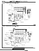
Piston O.D. “A”
6EN0554
.ower bearing
Upper bearing
(for No.
1,2.4,5)
Upper and lower bearings
(for center)
1
EN027:
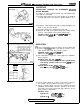
CYLINDER BORING
(1) Oversize pistons to be used should be determined on the
basis of the largest bore cylinder. .
Piston size identification
’
I
Size
I
Ideitification
mark
1
0.25
mm
(.Ol in.) O.S.
‘.
0.25
0.50
mm
(.02
in.) O.S.
‘”
0.50
0.75
mm
(.03
in.) O.S.
0.75
1.00
mm
(.04
in.)
O.S.
1
.oo
NOTE
Size mark is stamped on the piston top.
(2) Measure outside diameter of piston to be used. Measure it
in thrust direction as shown.
*
(3) Based on the measured piston O.D.; calculate the boring
finish dimension.
Boring finish dimension
=
Piston O.D.
+
(clearance
between piston O.D. and cylinder)
-
0.02 mm
(.OOOS
in.)
(honing margin)
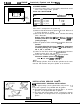
(4) Bore all cylinders to the calculated boiing finish dimension.
Caution
To prevent distortion that may
res
-It
from temperature
rise during honing, bore cylinders,
x1
the order of No. 2,
No. 4, No. 1 and No. 3.
(5) Hone to final finish dimension
[pisGn
0-D.
+
clearance
between piston O.D. and cylinder.],-
(6) Check the clearance between
pisto?r
and cylinder.
Clearance between piston and cdinder:
0.01
-
0.03 mm
(.0004
-
.0012
in.)
NOTE
When boring cylinders, finish all of four cylinders to the same
oversize. Do not bore only one cylinder to an oversize.
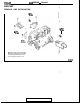
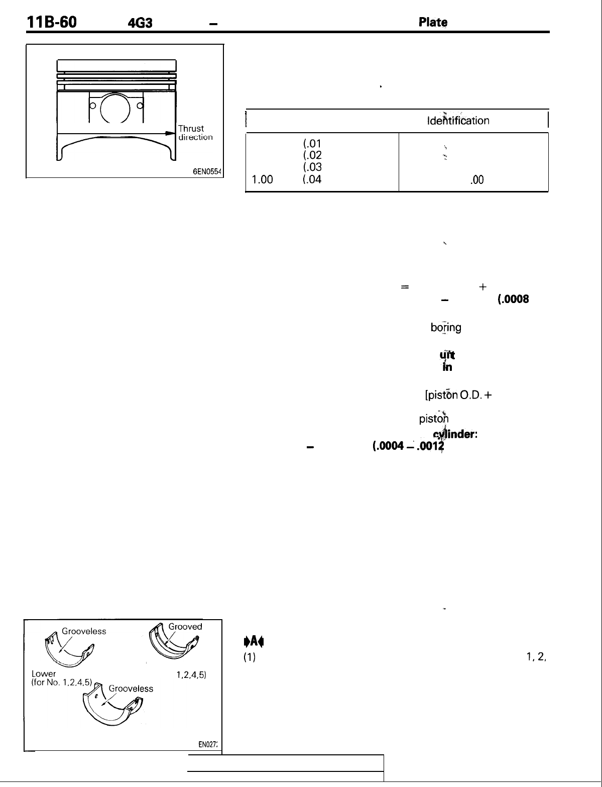
INSTALLATION SERVICE POINTS
*A4
CRANKSHAFT BEARING INSTALLATION
(1)
The upper bearings (on the cylinder block side) for Nos. 1,2,
4 and 5 journals are provided with oil groove.
(2) The lower bearings (on the cap side) for Nos. 1, 2, 4 and 5
journals are not provided with oil groove.
(3) The upper and lower bearings for No. 3 journal are common
parts which are flanged and are not provided with oil
groove.
TSB
Revision
I