
Service manual

4G6
ENGINE
<1993>
-
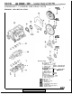
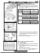
Piston and Connecting Rod
1
lww7
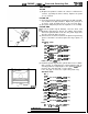
Press pin
-8
‘,j:::.@:::
Front mark
Connecting rod
guide
pin
”
1
Locknut
Stop screw
~
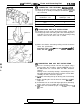
(3) Place the base on press support blocks.
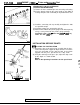
(4) Slide the piston pin over the threaded end of the press pin,
and thread the correct guide pin up against it.
(5) Coat the piston pin with oil, and with the connecting rod
held in position, slide the guide pin through the piston and
connecting rod.
(6) Press the piston pin through the connecting rod until the
guide pin contacts the stop screw.
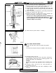
(7) Remove the piston assembly from the base. Remove the
guide pin and press pin from the assembly.
IMPORTANT:
Due to production tolerance variations, it
is necessary to visually inspect the piston pin depth
after installation to verify that the piston
pin
is
centered. Adjust if necessary.
7EN042:
(8) Check that the piston moves smoothly.
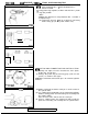
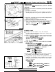
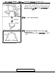
Side rail gap
1
EN0261
I)B4
OIL RING INSTALLATION
(1) Fit the oil ring spacer into the piston ring groove.
NOTE
The side rails and spacer may be installed in either direction.
(2) Install the upper side rail.
To install the side rail, first fit one end of the rail into the
piston groove, then press the remaining portion into
position by finger. See illustration.
Caution
Do not use piston ring expander when installing side
rail.
(3) Install the lower side rail in the same procedure as
described in step (2).
(4) Make sure that the side rails move smoothly in either
direction.
TSB
Revision