1A-0-1 ENGINE 4G9 SERIES CONTENTS GENERAL INFORMATION . . . . . . . . . . . . . . . . . . . . . . . . . . . . . . . . . . . . . . . . . . . 11A-0-3 1. SPECIFICATIONS . . . . . . . . . . . . . . . . . . . . . . . . . . . . . . . . . . . . . . . . . . . . . . . . 11A-1-1 SERVICE SPECIFICATIONS . . . . . . . . . . . . . . . . . . . . . . . . . . . . . . . . . . . . 11A-1-1 REWORK DIMENSIONS . . . . . . . . . . . . . . . . . . . . . . . . . . . . . . . . . . . . . . . . 11A-1-4 TORQUE SPECIFICATIONS ........
11A-0-2 NOTES E Mitsubishi Motors Corporation May 1995 PWEE9502
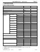
4G9 ENGINE (E - W) - General Information 11A-0-3 GENERAL INFORMATION 4G92 Descriptions 4G92- SOHC 4G92- DOHC- MIVEC Type In-line OHV, SOHC In-line OHV, DOHC Number of cylinders 4 4 Combustion chamber Pentroof type Pentroof type Total displacement dm3 1,597 1,597 Cylinder bore mm 81.0 81.0 Piston stroke mm 77.5 77.5 Compression ratio 10.0 11.0 Opens (BTDC) 20_, 14_* 17_ (Low-speed cam) 47.5_ (High-speed cam) Closes (ABDC) 42_, 58_* 31_ (Low-speed cam) 72.
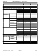
11A-0-4 4G9 ENGINE (E - W) - General Information 4G93 Descriptions 4G93 - SOHC 4G93 - DOHC 4G93 - DOHC - GDI Type In-line OHV, SOHC In-line OHV, DOHC In-line OHV, DOHC Number of cylinders 4 4 4 Combustion chamber Pentroof type Pentroof type Pentroof type Total displacement dm3 1,834 1,834 1,834 Cylinder bore mm 81.0 81.0 81.0 Piston stroke mm 89.0 89.0 89.0 Compression ratio 10.0, 9.5 10.5 11.7*1, 12.
4G9 ENGINE (E–W) – General Information 11A-0-5 4G94 Descriptions 4G94–SOHC 4G94–DOHC–GDI Type In-line OHV, SOHC In-line OHV, DOHC Number of cylinders 4 4 Combustion chamber Pentroof type Pentroof type Total displacement dm3 1,999 1,999 Cylinder bore mm 81.5 81.5 Piston stroke mm 95.8 95.8 Compression ratio 9.5 10.
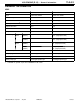
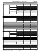
11A-1-1 4G9 ENGINE (E–W) – Specifications 1. SPECIFICATIONS SERVICE SPECIFICATIONS Items Standard value Limit Auto-tensioner rod protrusion amount (When removed from engine) mm 11 – Auto-tensioner rod stroke mm Within 1 – Auto-tensioner rod protrusion amount (When checking with installed on engine) mm 3.8 – 4.5 – Intake 37.34 36.84 Exhaust 36.79 36.29 Intake 37.78 37.28 Exhaust 37.83 37.33 Intake 36.92 36.42 Exhaust 36.70 36.65 Intake 37.53 37.03 Exhaust 37.64 37.
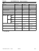
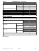
11A-1-2 4G9 ENGINE (E–W) – Specifications Items Standard value Limit Cylinder head gasket surface flatness mm Less than 0.03 0.2 Grinding limit of cylinder head gasket surface mm *Total resurfacing depth of both cylinder head and cylinder block – 0.2* Cylinder head overall height mm SOHC 119.9 – 120.1 – DOHC 131.9 – 132.1 – DOHC–MIVEC 119.8 – 120.0 – DOHC–GDI 131.9 – 132.1 – Intake 1.0 0.5 Exhaust 1.3 0.8 Intake 1.0 0.5 Exhaust 1.2 0.7 Intake 110.15 109.
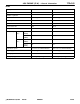
11A-1-3 4G9 ENGINE (E–W) – Specifications Items Standard value Limit Intake 49.30 49.80 Exhaust 49.35 49.85 Intake 46.70 47.20 Exhaust 46.65 47.15 Intake 58.13 58.63 Exhaust 57.85 58.35 Intake 46.70 47.20 Exhaust 46.65 47.15 Cylinder head bolt shank length mm – 96.4 Valve stem O.D. mm 6.0 – Valve face angle 45_ – 45.5_ – SOHC 216/44.2 – DOHC 255/44.5 – DOHC–MIVEC 255/44.5 – DOHC–GDI 196/37.5 – 6.0 – Oil pump tip clearance mm 0.06 – 0.
11A-1-4 4G9 ENGINE (E–W) – Specifications Items Standard value Limit 4G92 243.5 – 4G93 263.5 – 4G94 286.7 – 4G92, 4G93 81.0 – 4G94 81.5 – Piston to cylinder clearance mm 0.02 – 0.04 – Bearing cap bolt shank length mm – 71.1 Crankshaft end play mm 0.05 – 0.25 0.4 Crankshaft journal O.D. mm 50 – Crankshaft pin O.D. mm 45 – Cylinder block overall height mm Cylinder block I.D.
4G9 ENGINE (E–W) – Specifications 11A-1-5 TORQUE SPECIFICATIONS Items Nm Alternator and ignition system Oil level gauge 13 Distributor 12 Ignition coil 10 Spark plug 25 Crankshaft bolt 182 ± 4 Alternator brace (M8) 23 Alternator brace (M10) 49 Lock bolt 23 Adjusting bolt 5 Power steering pump pulley 25 Power steering pump bracket stay 49 Power steering pump bracket (M8) 21 Power steering pump bracket (M10) 44 Alternator pivot bolt 44 Center cover 3 Ignition failure sensor (
A-1-6 4G9 ENGINE (E–W) – Specifications Items Nm Fuel system and emission system Breather tube 21 Fuel pump 18 Carburetor 17 EGR valve 21 Cover 12 Fuel return pipe 9 Delivery pipe 12 Fuel pressure regulator 9 Throttle body stay 23 Throttle body stay <4G94> 24 Throttle body 19 Throttle cable bracket 19 Stay 24 Harness bracket 11 Vacuum hose and pipe assembly (Flange bolt) 11 Vacuum hose and pipe assembly
4G9 ENGINE (E–W) – Specifications Items 11A-1-6a Nm Intake manifold and exhaust manifold Exhaust manifold (M8) 18 Exhaust manifold (M10) 29 Exhaust manifold bracket (M8) 19 Exhaust manifold bracket (M10 Bolt and washer assembly) 35 Exhaust manifold bracket (M10 Flange bolt) 98 Engine hanger (Bolt with head mark “4”) 12 Engine hanger (Bolt with head mark “7”) 19 Oil level gauge guide 14 Boost sensor 5 Intake air temperature sensor 13 Heat protector 13 Intake manifold 20 Intake mani
11A-1-6b 4G9 ENGINE (E–W) – Specifications Items Nm Exhaust manifold (M8) 17 Exhaust manifold (M10) 29 Injector and fuel pump assembly (GDI) Fuel low pressure pipe (M6) 18 Fuel low pressure pipe (M8) 9 Fuel nipple 9 Clamp 9 Fuel feed pipe 11 Fuel pump 17 Harness bracket 11 Fuel pipe 11 Fuel return pipe 11 Fuel return pipe clamp 9 Fuel high pressure regulator 18 Fuel pressure sensor 23 Fuel pressure sensor 18 Spacer 18 Pump camshaft c
4G9 ENGINE (E–W) – Specifications Items Nm Water inlet fitting 19 Water inlet fitting 24 Water by-pass fitting 24 Water pipe 14 Water outlet fitting 19 Water outlet fitting 24 Engine coolant temperature gauge unit 10 Engine coolant temperature sensor 29 Water fitting 24 11A-1-6c Rocker arms and camshaft Lock nut 9 Rocker arm shaft 31 Harness bracket 10 Rocker cover 3.
11A-1-6d 4G9 ENGINE (E–W) – Specifications Items Nm Upper oil pan (M8) 24 Lower oil pan 11 Cover 7 Baffle plate 7 Baffle plate 11 Drain plug 39 Oil pressure switch 10 Transmission stay 23 Piston and connecting rod Connecting rod cap nut 20 + 90_ to 100_ Crankshaft, cylinder block, flywheel and drive plate Bearing cap bolt 25 + 90_ to 100_ Oil seal case 11 Bell housing cover (Flange bolt) 10 Bell housing cover (Bolt and washer assembly) 9 Rear plate
11A-1-7 4G9 ENGINE (E - W) - Specifications NEW TIGHTENING METHOD - BY USE OF BOLTS TO BE TIGHTENED IN PLASTIC AREA A new type of bolts, to be tightened in plastic area, is currently used for some parts of the engine. The tightening method for bolts of this type is different from the conventional one. Be sure to observe the method described in the text when tightening the bolts. Service limits are provided for the bolts. Make sure that the service limits described in the text are strictly observed.
11A-1-8 4G9 ENGINE (E - W) - Specifications FORM-IN-PLACE GASKET The engine has several areas where the form-in-place gasket (FIPG) is in use. To ensure that the gasket fully serves its purpose, it is necessary to observe some precautions when applying the gasket. Bead size, continuity and location are of paramount importance. Too thin a bead could cause leaks. Too thick a bead, on the other hand, could be squeezed out of location, causing blocking or narrowing of the fluid feed line.
4G9 ENGINE (E - W) - Special Tools 11A-2-1 2. SPECIAL TOOLS Tool E Mitsubishi Motors Corporation Number Name Use MB990938 Handle Use with MD998776 MB990767 Crankshaft pulley holder Holding camshaft sprocket when loosening and tightening of bolt.
11A-2-2 Tool E Mitsubishi Motors Corporation 4G9 ENGINE (E - W) - Special Tools Number Name Use MD998719 Pulley holder pin (2) Use with MB990767 MD998727 Oil pan remover Removal of the oil pan MD998754 Pin Use with MB990767 MD998767 Tensioner pulley socket wrench Adjustment of timing belt tension MD998772 Valve spring compressor Removal and installation of valve and related parts MD998774 Valve stem seal installer Installation of valve stem seal MD998775 Valve stem seal installer In
4G9 ENGINE (E - W) - Special Tools Tool E Mitsubishi Motors Corporation 11A-2-3 Number Name Use MD998780 SETTING TOOL Piston pin Removal and installation of piston pin MD998735 Valve spring compressor Compression of valve spring MD998781 Flywheel stopper Holding flywheel and drive plate MB991477 Valve adjusting wrench Adjustment of valve clearance (MIVEC) MB991478 Valve adjusting wrench feeler gauge set Adjustment of valve clearance (MIVEC) MB991479 Rocker arm piston checker Adjustmen
11A-3-1 4G9 ENGINE (E–W) – Alternator and Ignition System 3. ALTERNATOR AND IGNITION SYSTEM REMOVAL AND INSTALLATION (Engines with distributor) 7 12 Nm 8 25 Nm 9 5 Nm 23 Nm 2 3 10 44 Nm 23 Nm 49 Nm 21 Nm 13 12 1 44 Nm 49 Nm 6 11 44 Nm 4 5 25 Nm 182 ± 4 Nm Removal steps 1. Drive belt* 2. Alternator 3. Alternator brace AA" "BA 4. Crankshaft bolt "BA 5. Crankshaft pulley "BA 6. Front flange 7. Spark plug cable E Mitsubishi Motors Corporation Apr. 2002 8. 9. 10. 11. 12. 13.
11A-3-2 4G9 ENGINE (E–W) – Alternator and Ignition System REMOVAL AND INSTALLATION (Engines without distributor) 7 10 Nm 11 9 Nm 12 13 Nm 8 9 25 Nm 10 5 Nm 2 13 21 Nm 5 Nm 23 Nm 3 44 Nm 23 Nm 21 Nm 49 Nm 16 15 1 49 Nm 6 4 44 Nm 5 25 Nm 182 ± 4 Nm Removal steps 1. Drive belt* 2. Alternator 3. Alternator brace AA" "BA 4. Crankshaft bolt "BA 5. Crankshaft pulley "BA 6. Front flange 7. Spark plug cable 8. Ignition coil 9. Spark plug 10.
11A-3-2a 4G9 ENGINE (E–W) – Alternator and Ignition System REMOVAL AND INSTALLATION (Engines without distributor) 10 Nm 8 7 5 Nm 7 9 Nm 10 Nm 12 10 8 11 9 25 Nm 21 Nm 13 5 Nm 13 Nm 14 44 Nm 23 Nm 3 23 Nm 2 21 Nm 49 Nm 16 17 6 5 1 49 Nm 44 Nm 4 182 ± 4 Nm 44 Nm 15 25 Nm Removal steps 1. Drive belt* 2. Alternator 3. Alternator brace AA" "BA 4. Crankshaft bolt "BA 5. Crankshaft pulley "BA 6. Front flange 7. Spark plug cable 8. Ignition coil 9. Spark plug 10.
11A-3-2b 4G9 ENGINE (E - W) - Alternator and Ignition System Intentionally blank E Mitsubishi Motors Corporation Dec.
11A-3-3 4G9 ENGINE (E–W) – Alternator and Ignition System REMOVAL AND INSTALLATION 7 3 Nm 10 Nm 9 8 10 25 Nm 11 5 Nm 23 Nm 23 Nm 2 3 44 Nm 21 Nm 23 Nm 29 Nm 5 6 14 13 182 ± 4 Nm 1 4 44 Nm 49 Nm 44 Nm 12 25 Nm Removal steps 1. Drive belt* 2. Alternator 3. Alternator brace AA" "BA 4. Crankshaft bolt "BA 5. Crankshaft pulley "BA 6. Front flange 7. Center cover 8. Ignition coil E Mitsubishi Motors Corporation Nov. 1995 Apr. 2002 9. 10. 11. 12. 13. 14.
11A-3-4 4G9 ENGINE (E–W) – Alternator and Ignition System REMOVAL AND INSTALLATION 7 3 Nm 10 Nm 9 Nm 8 11 13 Nm 9 10 5 Nm 23 Nm 25 Nm 12 2 21 Nm 3 13 44 Nm 21 Nm 23 Nm 5 49 Nm 6 182 ± 4 Nm 16 15 1 4 44 Nm 49 Nm 44 Nm 14 25 Nm Removal steps 1. Drive belt* 2. Alternator 3. Alternator brace AA" "BA 4. Crankshaft bolt "BA 5. Crankshaft pulley "BA 6. Front flange 7. Center cover 8. Spark plug cable 9. Ignition coil E Mitsubishi Motors Corporation Nov. 1995 Apr.
11A-3-5 4G9 ENGINE (E–W) – Alternator and Ignition System REMOVAL AND INSTALLATION 2.9 Nm 7 14 5 Nm 10 Nm 9 8 9 Nm 11 25 Nm 10 12 13 2 13 Nm 21 Nm 5 Nm 23 Nm 3 44 Nm 23 Nm 21 Nm 6 5 49 Nm 17 16 1 44 Nm 49 Nm 4 44 Nm 182 ± 4 Nm Removal steps 1. Drive belt* 2. Alternator 3. Alternator brace AA" "BA 4. Crankshaft bolt "BA 5. Crankshaft pulley "BA 6. Front flange 7. Engine cover 8.
11A-3-6 4G9 ENGINE (E–W) – Alternator and Ignition System REMOVAL AND INSTALLATION 10 Nm 13 9 Nm 25 Nm 15 14 13 Nm 17 16 21 Nm 5 Nm 5 23 Nm 1 6 13 Nm 3 2 44 Nm 23 Nm 44 Nm 182 ± 4 Nm 8 3 9 21 Nm 4 11 7 12 49 Nm 44 Nm 10 44 Nm 25 Nm Removal steps 1. Oil level gauge 2. Oil level gauge guide 3. O-ring 4. Drive belt* 5. Alternator 6. Alternator brace AA" "BA 7. Crankshaft bolt "BA 8. Crankshaft pulley "BA 9. Front flange E Mitsubishi Motors Corporation Nov.
4G9 ENGINE (E–W) – Alternator and Ignition System 11A-3-7 REMOVAL SERVICE POINT AA" CRANKSHAFT BOLT REMOVAL (1) Use the special tool to hold the flywheel or the drive plate, and then loosen the crankshaft mounting bolts. MD998781 INSTALLATION SERVICE POINTS "AA CAM POSITION SENSOR SUPPORT INSTALLATION (1) Apply a 3 mm bead of form-in-place gasket (FIPG) to the area shown. Specified sealant: Mitsubishi Genuine equivalent. Part No.
4G9 ENGINE (E–W) – Timing Belt 11A-4-1 4. TIMING BELT REMOVAL AND INSTALLATION 14 88 Nm 13 11 Nm 1 7 4 5 6 8 11 Nm 11 Nm 11 10 9.8 Nm 12 9 23 Nm 3 2 49 Nm Removal steps 1. Timing belt front upper cover 2. Timing belt front lower cover 3. Engine support bracket, right AA" "DA 4. Timing belt "CA 5. Tensioner spring "BA 6. Timing belt tensioner 7.
11A-4-1a 4G9 ENGINE (E–W) – Timing Belt REMOVAL AND INSTALLATION 88 Nm 14 13 1 4 11 Nm 5 7 8 6 11 Nm 9.8 Nm 11 Nm 11 10 12 9 23 Nm 49 Nm 2 3 Removal steps 1. Timing belt front upper cover 2. Timing belt front lower cover 3. Engine support bracket, right AA" "DA 4. Timing belt "CA 5. Tensioner spring "BA 6. Timing belt tensioner 7. Timing belt rear cover 8.
4G9 ENGINE (E - W) - Timing Belt 11A-4-1b Intentionallyblank E Mitsubishi Motors Corporation May 2000 PWEE9502-G Added
11A-4-2 4G9 ENGINE (E–W) – Timing Belt REMOVAL AND INSTALLATION 88 Nm 14 13 1 11 Nm 11 Nm 23 Nm 7 6 5 8 3 10 11 12 9.8 Nm 9 4 49 Nm 2 Removal steps 1. Timing belt front upper cover 2. Timing belt front lower cover 3. Accessory mount AA" "DA 4. Timing belt "CA 5. Tensioner spring "BA 6. Timing belt tensioner 7. Timing belt rear cover E Mitsubishi Motors Corporation Mar. 2001 8. Crankshaft angle sensor "GA 9. Crankshaft sprocket "GA 10. Crankshaft spacer "GA 11.
11A-4-2a 4G9 ENGINE (E–W) – Timing Belt REMOVAL AND INSTALLATION 19 11 Nm 4 88 Nm 18 17 5 24 Nm 11 Nm 1 6 10 36 Nm 7 1416 11 15 44 Nm 11 Nm 13 20 9 11 Nm 9.8 Nm 8 12 13 Nm 3 2 49 Nm Removal steps 1. Timing belt upper cover 2. Timing belt lower cover 3. Engine support bracket AA" "FA 4. Timing belt 5. Tensioner pulley 6. Tensioner arm 7. Shaft "EA 8. Auto-tensioner 9. Timing belt rear cover 10. Idler pulley E Mitsubishi Motors Corporation Mar.
11A-4-2b 4G9 ENGINE (E–W) – Timing Belt REMOVAL AND INSTALLATION 18 88 Nm 11 Nm 4 17 16 5 48 Nm 1 11 Nm 10 6 7 35 Nm 48 Nm 15 12 14 13 11 Nm 19 11 Nm 9 3 13 Nm 8 9.8 Nm 2 11 49 Nm Removal steps 1. Timing belt front upper cover 2. Timing belt front lower cover 3. Engine support bracket, right AA" "FA 4. Timing belt 5. Tensioner pulley 6. Tensioner arm 7. Shaft "EA 8. Auto tensioner 9. Timing belt rear cover 10. Idler pulley E Mitsubishi Motors Corporation Mar. 2001 11.
11A-4-2c 4G9 ENGINE (E–W) – Timing Belt REMOVAL AND INSTALLATION 21 11 Nm 11 Nm 19 4 88 Nm 18 17 11 Nm 1 5 6 7 10 48 Nm 35 Nm 13 12 9 8 12 2 Removal steps 1. Timing belt front upper cover 2. Timing belt front lower cover 3. Engine support bracket, right AA" "FA 4. Timing belt 5. Tensioner pulley 6. Tensioner arm 7. Shaft "EA 8. Auto tensioner 9. Timing belt rear cover 10. Idler pulley 11. Crankshaft angle sensor (Up to 1999 model) 12.
11A-4-2d 4G9 ENGINE (E–W) – Timing Belt REMOVAL AND INSTALLATION 18 11 Nm 4 88 Nm 17 16 11 Nm 1 7 5 6 10 48 Nm 35 Nm 13 15 14 48 Nm 12 9 3 8 11 Nm 49 Nm 13 Nm 9.8 Nm 11 2 Removal steps 1. Timing belt front upper cover 2. Timing belt front lower cover 3. Engine support bracket, right AA" "FA 4. Timing belt 5. Tensioner pulley 6. Tensioner arm 7. Shaft "EA 8. Auto tensioner 9. Timing belt rear cover E Mitsubishi Motors Corporation Mar.
11A-4-2e 4G9 ENGINE (E–W) – Timing Belt REMOVAL AND INSTALLATION 21 11 Nm 19 11 Nm 4 18 88 Nm 17 5 1 11 Nm 6 10 7 15 48 Nm 20 14 16 35 Nm 12 48 Nm 13 11 Nm 9 11 Nm 11 11 Nm 9.8 Nm 8 49 Nm 13 Nm 3 2 Removal steps 1. Timing belt front upper cover 2. Timing belt front lower cover 3. Accesory mount AA" "FA 4. Timing belt 5. Tensioner pulley 6. Tensioner arm 7. Shaft "EA 8. Auto tensioner 9. Timing belt rear cover 10.
11A-4-2f 4G9 ENGINE (E - W) - Timing Belt Intentionallyblank E Mitsubishi Motors Corporation May 2000 PWEE9502-G Added
4G9 ENGINE (E - W) - Timing Belt 11A-4-3 REMOVAL SERVICE POINTS AA" TIMING BELT REMOVAL (1) Mark belt running direction for reinstallation. AB" CAMSHAFT SPROCKET BOLT REMOVAL MB990767 MD998719 or MD998754 (Except SOHC) (1) Use a wrench to hold the hexagonal part of the camshaft, and then remove the camshaft sprocket mounting bolt. INSTALLATION SERVICE POINTS MB990767 "AA CAMSHAFT SPROCKET BOLT INSTALLATION MD998719 or MD998754 E Mitsubishi Motors Corporation Nov.
11A-4-4 4G9 ENGINE (E - W) - Timing belt "BA TIMING BELT TENSIONER INSTALLATION (1) Let the pulley of the timing belt tensioner comr closest to the exhaust side. Temporarily tighten the tensioner pulley fixing bolt. Exhaust side Tensioner pulley fixing bolt Tensioner “B” “A” "CA TENSIONER SPRING INSTALLATION (1) Insert the tip A (shorter one) of the tensioner spring into the oil pump case. (2) Use pliers or similar tool to pinch the tip B (longer one), and then hook it to the tensioner bracket arm.
4G9 ENGINE (E - W) - Timing Belt 11A-4-5 (6) Slightly loosen the tensioner pulley fixing bolt which is tightened temporarily to tighten the belt by a force of the tensioner spring. (7) Turn the crankshaft clockwise by two turns. (8) Check that the timing marks are aligned. (9) Tighten the fixing bolt of the tensioner pulley. MD998716 Set hole (A) Set hole (B) "EA AUTO-TENSIONER INSTALLATION (1) If the auto-tensioner rod is fully extended, set it in the retracted position with the following procedure.
11A-4-6 4G9 ENGINE (E - W) - Timing Belt "FA TIMING BELT INSTALLATION (1) Make sure that the auto-tensioner is installed properly. (Refer to service point F.) (2) Align the timing mark on each sprocket with the corresponding mark on the timing belt. (3) Turn the crankshaft sprocket one half the tooth width counterclockwise. Timing marks Timing mark Paper clip (4) Fit the timing belt to the intake camshaft sprocket and secure with a paper clip at the illustrated position.
4G9 ENGINE (E - W) - Timing Belt 11A-4-7 (6) Secure the timing belt with a paper clip at the illustrated position. Idler pulley (7) Fit the belt to the idler pulley water pump sprocket, crankshaft sprocket and tensioner pulley in that order. Water pump sprocket Tensioner pulley Crankshaft sprocket (8) Raise the tensioner pulley in the direction of an arrow and tighten the tensioner pulley bolt. (9) Remove the two paper clips. (10)Make sure that all timing marks are in alignment.
11A-4-8 4G9 ENGINE (E–W) – Timing Belt (12)Install the special tool and a torque wrench to the tensioner pulley. (13)Using torque wrench, torque to 2.6 Nm. (14)While holding the tensioner pulley to prevent it from turning, tighten the center bolt to the specified torque. (15)Give two clockwise turns to the crankshaft and leave as it is for approx. 15 minutes. (16)Check if the Allen wrench inserted during installation of the auto-tensioner can be pulled out lightly.
4G9 ENGINE (E - W) - Timing Belt 11A-4-9 (6) Abnormal wear of belt sides. The sides are normal if they are sharp as if cut by a knife. Rounded edge Abnormal wear (Fluffy strand) (7) Abnormal wear on teeth. (8) Missing tooth. Rubber exposed Tooth missing and canvas fiber exposed TENSIONER PULLER, IDLER PULLEY (1) Check the pulley for smooth rotation, excessive play, abnormal noise. Replace it if necessary. AUTO-TENSIONER (1) Check the tensioner for oil leaks. Replace it if necessary.
4G9 ENGINE (E - W) - Fuel and Emission Control System 11A-5-1 5. FUEL AND EMISSION CONTROL SYSTEM REMOVAL AND INSTALLATION 18 Nm 17 Nm 21 Nm 8 3 10 4 9 11 5 6 2 7 1 21 Nm Removal steps 1. Breather tube 2. Fuel hose 3. Fuel hose 4. Fuel pump 5. Gasket 6. Insulator 7. Gasket 8. Carburetor 9. Gasket 10. EGR valve 11. Gasket E Mitsubishi Motors Corporation Nov.
11A-5-2 4G9 ENGINE (E–W) – Fuel and Emission Control System REMOVAL AND INSTALLATION 12 Nm 9 Nm 10 16 19 Nm 17 2 15 13 12 Engine with solenoid valve Flange 11 Nm Engine with solenoid valve Washer 9 Nm Engine without solenoid valve 10Nm 14 3 19 21 1 21 Nm 11 7 24 Nm 4 20 6 12 Nm 9 5 8 18 9 Nm 9 Nm Removal steps 1. Vacuum hose and pipe assembly 2. Throttle body "CA 3. Gasket 4. Engine hanger (4G94) 5. Throttle body stay (4G94) 6. Vacuum hose 7.
4G9 ENGINE (E–W) – Fuel and Emission Control System 11A-5-3 REMOVAL AND INSTALLATION 9 Nm 12 Nm 8 18 24 Nm 17 19 Nm 1 11 5 16 15 14 13 3 11 Nm 6 2 12 22 Nm 4 9 Nm 20 21 7 19 9 9 Nm 10 9 Nm Removal steps 1. Stay (From 2002 model) 2. Harness bracket 3. Throttle cable bracket 4. Vacuum hose and pipe assembly 5. Throttle body "CA 6. Gasket 7. Vacuum hose 8. Fuel hose "BA 9. Fuel pressure regulator 10. O-ring 11.
11A-5-4 4G9 ENGINE (E–W) – Fuel and Emission Control System REMOVAL AND INSTALLATION 11 Nm 9 Nm 17 4 15 14 12 11 13 2 9 10 Nm 18 Nm 23 Nm 3 1 23 Nm 10 9 Nm 16 6 5 8 7 9 Nm Removal steps 1. Vacuum pipe assembly 2. Throttle body assembly "CA 3. Gasket 4. Throttle body stay (MIVEC) 5. Vacuum hose 6. Fuel hose "BA 7. Fuel pressure regulator 8. O-ring 9. Delivery pipe and injector E Mitsubishi Motors Corporation Nov. 1996 Jun. 2002 10. 11. "AA 12. 13. 14. 15. 16. 17.
4G9 ENGINE (E - W) - Fuel and Emission Control System 11A-5-5 INSTALLATION SERVICE POINTS "AA INJECTORS INSTALLATION (1) Apply a small amount of new engine oil to the O-ring. Caution Be sure not to let engine oil get into the delivery pipe. Injector connector A B (2) While turning the injector to the left and right, install it to the delivery pipe. (3) Check that the injector turns smoothly. If it does not turn smoothly, the O-ring may be trapped.
11A-5-6 4G9 ENGINE (E - W) - Fuel and Emission Control System Projection E Mitsubishi Motors Corporation Dec.
4G9 ENGINE (E - W) - Throttle Body and EGR System (GDI) 11A-5a-1 5a. THROTTLE BODY AND EGR SYSTEM (GDI) REMOVAL AND INSTALLATION 18 Nm 6 7 4 17 12 3 2 15 16 18 Nm 18 Nm 9 Nm 14 9 Nm 13 14 24 Nm 18 Nm 30 Nm 1 10 18 Nm Removal steps 1. Air intake plenum resonator 2. O-ring "BA 3. Intake manifold stay 4. Water hose 5. Water hose (Up to 1998 model for CARISMA, SPACE RUNNER) 6. Throttle body "AA 7. Throttle body gasket 8.
11A-5a-2 4G9 ENGINE (E–W) – Throttle Body and EGR System (GDI) REMOVAL AND INSTALLATION 18 Nm 2 6 3 7 24 Nm 5 8 4 12 11 20 Nm 24 Nm 12 10 30 Nm 9 24 Nm 18 Nm 1 Removal steps "BA 1. Intake manifold stay (For GALANT) 2. Water hose 3. Water hose 4. Water hose 5. Throttle body stay 6. Throttle body E Mitsubishi Motors Corporation Apr. 2003 PWEE9502-L "AA 7. 8. 9. 10. 11. 12.
4G9 ENGINE (E - W) - Throttle Body and EGR System (GDI) 11A-5a-3 REMOVAL AND INSTALLATION 1 14 9 18 Nm 13 18 Nm 23 Nm 7 14 11 Nm 12 10 11 3 16 15 5 13 Nm 6 18 Nm 18 Nm 2 8 11 Nm 4 Removal steps 1. Water hose 2. Water hose 3. Water hose 4. Water hose 5. Water hose 6. Water hose clamp 7. Water pipe 8. Water pipe E Mitsubishi Motors Corporation July 2000 9. "AA 10. 11. 12. 13. 14. 15.
11A-5a-4 4G9 ENGINE (E - W) - Throttle Body and EGR System (GDI) REMOVAL AND INSTALLATION 1 18 Nm 15 14 18 Nm 23 Nm 18 Nm 11 Nm 14 7 13 9 11 12 3 10 6 13 Nm 16 18 Nm 5 18 Nm 2 8 11 Nm 4 Removal steps 1. Water hose 2. Water hose 3. Water hose 4. Water hose 5. Water hose 6. Water hose clamp 7. Water pipe 8. Water pipe E Mitsubishi Motors Corporation July 2000 9. 10. "AA 11. 12. 13. 14. 15. 16.
4G9 ENGINE (E - W) - Throttle Body and EGR System (GDI) 11A-5a-5 INSTALLATION SERVICE POINTS Tab "AA THROTTLE BODY GASKET Intake manifold Bolt Intake manifold stay "BA INTAKE MANIFOLD STAY INSTALLATION (1) Tighten the four bolts at the top and bottom of the stay handtight.
11A-6-1 4G9 ENGINE (E–W) – Intake and Exhaust Manifold 6. INTAKE AND EXHAUST MANIFOLD REMOVAL AND INSTALLATION 20 Nm 3 5 4 9 6 7 20 Nm 13 12 2 14 Nm Bolt with head mark “4” 12 Nm Bolt with head mark “7” 19 Nm 29 Nm 18 Nm 13 Nm 8 31 Nm 1 11 Bolt with head mark “4” 12 Nm Bolt with head mark “7” 19 Nm 10 13 Nm 19 Nm Removal steps 1. Engine hanger "BA 2. Intake manifold stay 3. Intake manifold 4. Intake manifold gasket 5. Oil level gauge 6.
11A-6-2 4G9 ENGINE (E–W) – Intake and Exhaust Manifold REMOVAL AND INSTALLATION 20 Nm Bolt with head mark “4” 12 Nm Bolt with head mark “7” 19 Nm 3 20 Nm 5 1 6 4 14 Nm 7 13 2 29 Nm 18 Nm 12 31 Nm 11 10 8 9 13 Nm 19 Nm Bolt with head mark “4” 12 Nm Bolt with head mark “7” 19 Nm Removal steps 1. Engine hanger 2. Intake manifold stay 3. Intake manifold 4. Intake manifold gasket 5. Oil level gauge 6.
11A-6-2a 4G9 ENGINE (E–W) – Intake and Exhaust Manifold REMOVAL AND INSTALLATION 3 20 Nm 19 Nm 5 1 20 Nm 6 4 7 14 Nm 8 13 2 44 Nm 30 Nm 18 Nm 13 Nm 31 Nm 10 12 14 9 19 Nm 19 Nm 13 Nm 11 35 Nm Removal steps 1. Engine hanger 2. Intake manifold stay 3. Intake manifold 4. Intake manifold gasket 5. Oil level gauge 6. Oil level gauge guide 7. O-ring E Mitsubishi Motors Corporation Nov. 1996 Mar. 2001 8. 9. 10. 11.
11A-6-2b 4G9 ENGINE (E–W) – Intake and Exhaust Manifold REMOVAL AND INSTALLATION 20 Nm 2 3 20 Nm 4 5 6 14 Nm 12 1 11 29 Nm 18 Nm 31 Nm 10 9 7 8 13 Nm 19 Nm 19 Nm Removal steps 1. Intake manifold stay 2. Intake manifold 3. Intake manifold gasket 4. Oil level gauge 5. Oil level gauge guide 6. O-ring E Mitsubishi Motors Corporation Nov. 2001 1996 Mar. 7. 8. "AA 9. "AA 10. 11. 12.
11A-6-2c 4G9 ENGINE (E–W) – Intake and Exhaust Manifold REMOVAL AND INSTALLATION 8 20 Nm 13 Nm 7 6 13 Nm 12 4 11 5 9 19 Nm 18 Nm 1 10 31 Nm 35 Nm 29 Nm 2 14 Nm 3 Removal steps 1. Oil level gauge 2. Oil level gauge guide 3. O-ring 4. Engine hanger 5. Intake manifold stay 6. Intake manifold E Mitsubishi Motors Corporation Nov. 1996 Jun. 2002 7. 8. 9. "AA 10. 11. 12.
11A-6-2d 4G9 ENGINE (E–W) – Intake and Exhaust Manifold REMOVAL AND INSTALLATION 20 Nm 8 13 Nm 7 6 13 Nm 12 4 5 11 9 19 Nm 18 Nm 35 Nm 1 31 Nm 1 29 Nm 10 2 14 Nm 3 Removal steps 1. Oil level gauge 2. Oil level gauge guide 3. O-ring 4. Engine hanger 5. Intake manifold stay 6. Intake manifold E Mitsubishi Motors Corporation Nov. 1996 Jun. 2002 7. 8. 9. "AA 10. 11. 12.
11A-6-2e 4G9 ENGINE (E–W) – Intake and Exhaust Manifold REMOVAL AND INSTALLATION 8 13 Nm 20 Nm 7 6 13 Nm 4 12 11 5 9 19 Nm 18 Nm 1 31 Nm 10 29 Nm 98 Nm 2 14 Nm 3 Removal steps 1. Oil level gauge 2. Oil level gauge guide 3. O-ring 4. Engine hanger 5. Intake manifold stay 6. Intake manifold E Mitsubishi Motors Corporation Nov. 1996 Jun. 2002 7. 8. 9. "AA 10. 11. 12.
11A-6-2f 4G9 ENGINE (E–W) – Intake and Exhaust Manifold Intentionally blank E Mitsubishi Motors Corporation Nov. 1996 Jun.
11A-6-3 4G9 ENGINE (E–W) – Intake and Exhaust Manifold REMOVAL AND INSTALLATION 20 Nm Bolt with head mark “4” Bolt with head mark “7” 12 Nm 19 Nm 3 1 20 Nm 4 12 11 2 29 Nm 18 Nm Bolt with head mark “4” Bolt with head mark “7” 31 Nm 12 Nm 19 Nm 5 8 10 6 9 7 14 Nm 19 Nm Removal steps 1. Engine hanger 2. Intake manifold stay 3. Intake manifold 4. Intake manifold gasket 5. Oil level gauge 6. Oil level gauge guide E Mitsubishi Motors Corporation Mar. Nov. 2001 1996 7. 8. "AA 9. "AA 10.
11A-6-4 4G9 ENGINE (E–W) – Intake and Exhaust Manifold INSTALLATION SERVICE POINT Bracket A Bracket B "AA EXHAUST MANIFOLD BRACKET INSTALLATION (1) Install temporarily the exhaust manifold brackets A and B as shown in the illustration. (2) Check that both brackets are in close contact with the bosses, and then tighten fully the bracket mounting bolts. Exhaust manifold (1) Temporarily install the exhaust manifold bracket as shown in the illustration.
11A-6a-1 4G9 ENGINE (E - W) - Intake Manifold (GDI) 6a. INTAKE MANIFOLD (GDI) REMOVAL AND INSTALLATION 1 11 Nm 9 Nm 6 8 11 Nm 5 11 Nm 4 9 Nm 3 2 19 Nm 7 9 10 19 Nm Removal steps 1. Air by-pass hose (Up to 1998 model for CARISMA, SPACE RUNNER) 2. Vacuum pipe and hose 3. Bracket 4. Solenoid valve E Mitsubishi Motors Corporation Jun. 1998 May 2000 5. 6. 7. 8. 9. 10.
11A-6a-1a 4G9 ENGINE (E–W) – Intake Manifold (GDI) REMOVAL AND INSTALLATION 2 19 Nm 11 Nm 19 Nm 11 Nm 4 3 1 5 Removal steps 1. Vacuum pipe and hose 2. Purge hose 3. Solenoid valve E Mitsubishi Motors Corporation Jun. 1998 Apr. 2003 4. Vacuum pipe 5.
4G9 ENGINE (E - W) - Intake Manifold (GDI) 11A-6a-1b Intentionallyblank E Mitsubishi Motors Corporation Jun.
11A-6a-2 4G9 ENGINE (E - W) - Intake Manifold (GDI) REMOVAL AND INSTALLATION 1 11 Nm 9 Nm 6 4 8 2 11 Nm 9 Nm 3 11 Nm 5 19 Nm 7 9 10 19 Nm Removal steps 1. Air by-pass hose 2. Vacuum pipe and hose 3. Bracket 4. Solenoid valve 5. Connector bracket E Mitsubishi Motors Corporation Jun. 1998 6. 7. 8. 9. 10.
4G9 ENGINE (E - W) - Intake Manifold (GDI) 11A-6a-3 REMOVAL AND INSTALLATION 9 Nm 6 1 4 7 11 Nm 9 Nm 9 3 9 Nm 23 Nm 19 Nm 2 9 Nm 10 11 Nm 5 8 30 Nm Removal steps 1. P.C.V. hose 2. Vacuum pipe and hose 3. Solenoid valve 4. Fuel pump protector 5. Connector bracket E Mitsubishi Motors Corporation Dec. 1998 6. 7. "AA 8. 9. 10.
11A-6a-4 4G9 ENGINE (E - W) - Intake Manifold (GDI) INSTALLATION SERVICE POINT "AA INTAKE MANIFOLD STAY INSTALLATION (1) Check to ensure that the intake manifold stay is in close contact with the intake manifold and the cylinder block before tightening the respective mounting bolts to the specified torque. Intake manifold Intake manifold stay Cylinder block E Mitsubishi Motors Corporation Dec.
11A-6b-1 4G9 ENGINE (E - W) - Exhaust Manifold (GDI) 6b. EXHAUST MANIFOLD (GDI) REMOVAL AND INSTALLATION 9 8 17 Nm 6 13 Nm 35 Nm 4 29 Nm 18 Nm 5 24 Nm 7 35 Nm 1 18 Nm 13 Nm 2 13 Nm 3 Removal steps 1. Oil level gauge 2. Oil level gauge guide 3. O-ring 4. Exhaust manifold cover 5. Engine hanger "AA 6. Exhaust manifold bracket A "AA 7. Exhaust manifold bracket B 8. Exhaust manifold 9.
11A-6b-1a REMOVAL AND INSTALLATION 10 4 9 17 Nm 44 Nm 13 Nm 6 8 29 Nm 5 19 Nm 24 Nm 1 7 13 Nm 11 2 35 Nm 35 Nm 13 Nm 3 Removal steps 1. Oil level gauge 2. Oil level gauge guide 3. O-ring 4. Oxygen sensor 5. Engine hanger 6. Exhaust manifold cover 7. Exhaust manifold bracket B 8. Heat protector 9. Exhaust manifold 10. Exhaust manifold gasket 11.
4G9 ENGINE (E - W) - Exhaust Manifold (GDI) 11A-6b-1b Intentionallyblank E Mitsubishi Motors Corporation May 2000 PWEE9502-G Added
11A-6b-2 4G9 ENGINE (E - W) - Exhaust Manifold (GDI) REMOVAL AND INSTALLATION 1 13 Nm 5 4 2 18 Nm 29 Nm 3 17 Nm 98 Nm 29 Nm Removal steps 1. Exhaust manifold cover 2. Engine hanger "BA 3. Exhaust manifold bracket 4. Exhaust manifold 5. Exhaust manifold gasket E Mitsubishi Motors Corporation Dec.
4G9 ENGINE (E - W) - Exhaust Manifold (GDI) 11A-6b-3 INSTALLATION SERVICE POINTS "AA EXHAUST MANIFOLD BRACKET INSTALLATION (1) Slide the washers over the bolts with the chamfered side toward the bolt. Bracket A Bracket B (2) Install temporarily the exhaust manifold brackets A and B as shown in the illustration. (3) Check that both brackets are in close contact with the bosses, and then tighten fully the bracket mounting bolts.
4G9 ENGINE (E - W) - Injector and Fuel Pump Assembly (GDI) 11A-6c-1 6c. INJECTOR AND FUEL PUMP ASSEMBLY (GDI) REMOVAL AND INSTALLATION 9 Nm 6 18 Nm 11 Nm 27 14 11 Nm 7 11 Nm 17 16 10 9 8 15 18 17 ± 2 Nm 11 Nm 4 35 36 37 33 31 22 Nm 28 29 May 2000 20 19 23 Nm 11 12 5 23 30 25 34 32 Removal steps 1. Fuel hose 2. Fuel low pressure pipe 3. O-ring 4. Fuel nipple 5. O-ring 6. Clamp "FA 7. Fuel feed pipe 8.
11A-6c-1a 4G9 ENGINE (E–W) – Injector and Fuel Pump Assembly (GDI) REMOVAL AND INSTALLATION 11 Nm 11 Nm 23 Nm 8 3 2 4 1 9 6 11 Nm 7 9 8 7 17 Nm 5 10 11 Nm 11 19 22 22 Nm 18 20 21 17 16 14 12 15 13 "IA "IA "IA "HA "HA "HA "HA "GA "GA Removal steps 1. Injector harness 2. Flange 3. Fuel pressure sensor 4. Backup ring 5. O-ring 6. Fuel pipe 7. Backup ring 8. O-ring 9. Backup ring 10. Fuel pump 11.
4G9 ENGINE (E - W) - Injector and Fuel Pump Assembly (GDI) 11A-6c-1b REMOVAL AND INSTALLATION 11 Nm 11 Nm 23 Nm 11 8 10 5 4 6 3 9 11 Nm 11 10 9 17 Nm 7 12 11 Nm 13 21 24 20 22 23 22 Nm 14 15 "IA "IA "IA "HA "HA "HA "HA "JA 2 19 18 1 16 17 Removal steps 1. Fuel hose 2. Fuel hose 3. Injector harness 4. Flange 5. Fuel pressure sensor 6. Backup ring 7. O-ring 8. Fuel pipe 9. Backup ring 10. O-ring 11. Backup ring 12.
11A-6c-2 4G9 ENGINE (E - W) - Injector and Fuel Pump Assembly (GDI) REMOVAL AND INSTALLATION 10 11 11 Nm 12 9 Nm 11 Nm 2 16 5 17 18 19 22 18 Nm 3 21 14 4 15 18 Nm 9 Nm 18 Nm 13 17 ± 2 Nm 11 Nm 7 6 23 35 31 33 34 20 9 8 24 32 9 Nm 30 22 Nm 29 27 25 26 28 Removal steps 1. Injector harness 2. Fuel hose 3. Fuel hose 4. Fuel hose 5. Fuel pipe 6. Fuel nipple 7. O-ring 8. Fuel nipple 9. O-ring "FA 10. Fuel feed pipe 11. Backup ring 12. O-ring 13.
4G9 ENGINE (E - W) - Injector and Fuel Pump Assembly (GDI) 11A-6c-3 INSTALLATION SERVICE POINTS "AA BACKUP RING / O-RING / CORRUGATED WASHER INSTALLATION (1) Attach the backup rings and O-ring to the injector. The thicker backup ring must be so installed that the inside cut surface is directed as shown in the illustration. Cut surface Backup ring (2) Coat the corrugated washer with white vaseline and install it to the injector as shown. Caution Always replace the corrugated washer with new one.
11A-6c-4 4G9 ENGINE (E - W) - (8) Tighten the fasteners of the delivery pipe and injector assembly to the specified torque in the order given in the illustration. 4 2 1 3 Injector and Fuel Pump Assembly (GDI) 3 O-ring 1 2 4 Coupling key Groove Camshaft "CA PUMP CAMSHAFT CASE INSTALLATION (1) Apply small amount of engine oil to the O-ring (larger one) on the case.
4G9 ENGINE (E - W) - Injector and Fuel Pump Assembly (GDI) 11A-6c-5 (2) Fit the backup rings and the O-ring on both ends of the fuel return pipe. Note that the larger backup ring must be installed with the inside cut surface in the direction shown in the illustration. (3) Lubricate the O-rings on both ends of the pipe with spindle oil or gasoline. (4) Insert the fuel return pipe ends straight in the respective mounting holes of the pressure regulator and the delivery pipe.
11A-6c-6 4G9 ENGINE (E - W) - Injector and Fuel Pump Assembly (GDI) "GA O-RING / FUEL PUMP INSTALLATION (1) Apply engine oil to the roller of the fuel pump and O-ring. (2) Insert the fuel pump into the mounting hole in the cylinder head and lightly tighten the four bolts. 1 3 4 2 Backup ring (no special orientation) Backup ring (thicker one) E Mitsubishi Motors Corporation Cut surface May 2000 (3) Using a torque wrench (minimum graduations of 0.
4G9 ENGINE (E - W) - Injector and Fuel Pump Assembly (GDI) 11A-6c-7 "IA O-RING / BACKUP RING / FUEL PRESSURE SENSOR INSTALLATION (1) Fit the backup ring to the fuel pressure sensor so that its inner cut surface faces in the direction shown. Backup ring Cut surface Fuel pressure sensor (2) Being attentive to the shape of the connector and label surface of the fuel pressure sensor, install the fuel pressure sensor in the direction shown.
4G9 ENGINE (E - W) - Intake and Exhaust Manifold <4G94 - GDI for PAJERO io> 11A-6d-1 6d. INTAKE AND EXHAUST MANIFOLD <4G94 - GDI for PAJERO io> REMOVAL AND INSTALLATION 1 9 Nm 9 Nm 4 3 9 5 20 Nm 23 Nm 2 9 Nm 10 8 13 Nm 11 11 Nm 15 6 14 7 12 29 Nm 18 Nm 13 31 Nm 17 Nm 98 Nm 29 Nm Removal steps 1. P.C.V. hose 2. Purge hose 3. Vacuum pipe and hose 4. Solenoid valve 5. Fuel pump protector 6. Connector bracket "BA 7. Intake manifold stay 8.
11A-6d-2 4G9 ENGINE (E - W) - Intake and Exhaust Manifold <4G94 - GDI for PAJERO io> INSTALLATION SERVICE POINTS "AA EXHAUST MANIFOLD BRACKET INSTALLATION (1) The washers must be installed with the shear-drooped side toward the bolts. Shear-droop (2) Temporarily install the exhaust manifold bracket as shown in the illustration. (3) Verify that the bracket is brought into close contact with the boss on the exhaust manifold, then tighten the bolts to the specified torque.
11A-7-1 4G9 ENGINE (E–W) – Water Pump and Water Hose 7. WATER PUMP AND WATER HOSE 11301790016 REMOVAL AND INSTALLATION 10 Nm 29 Nm 1 3 4 8 24 Nm 2 7 6 14 Nm 9 19 Nm 5 24 Nm 14 Nm 10 19 Nm 11 12 Removal steps 1. Water hose (Except carburetor engines) 2. Water hose "GA 3. Engine coolant temperature sensor "FA 4. Engine coolant temperature gauge unit "EA 5. Water outlet fitting E Mitsubishi Motors Corporation Nov. 1996 Jun.
11A-7-2 4G9 ENGINE (E–W) – Water Pump and Water Hose REMOVAL AND INSTALLATION 2 14 Nm 4 24 Nm 10 Nm 6 5 8 29 Nm 7 3 24 Nm 1 24 Nm 11 17 13 24 Nm 12 13 14 Nm 14 15 10 16 24 Nm 16 24 Nm 10 Removal steps 1. Water hose 2. Water hose 3. Water hose 4. Water pipe "GA 5. Engine coolant temperature sensor "FA 6. Engine coolant temperature gauge unit "IA 7. Water fitting "EA 8. Water outlet fitting E Mitsubishi Motors Corporation May Jun.
11A-7-3 4G9 ENGINE (E–W) – Water Pump and Water Hose REMOVAL AND INSTALLATION 10 Nm 29 Nm 1 3 4 24 Nm 8 2 7 6 14 Nm 9 24 Nm 19 Nm 5 14 Nm 10 19 Nm 11 12 Removal steps 1. Water hose A (Except GDI 2. Water hose B (Except GDI "GA 3. Engine coolant temperature "FA 4. Engine coolant temperature unit "EA 5. Water outlet fitting 6. Water inlet fitting E Mitsubishi Motors Corporation Nov. 1996 Jun.
11A-7-4 4G9 ENGINE (E–W) – Water Pump and Water Hose REMOVAL AND INSTALLATION 10 Nm 2 24 Nm 1 4 29 Nm 3 24 Nm 24 Nm 7 13 9 24 Nm 8 9 10 14 Nm 11 9 12 12 24 Nm 24 Nm 6 "GA "FA "IA "EA "DA Removal steps 1. Engine coolant temperature sensor 2. Engine coolant temperature gauge unit 3. Water fitting 4. Water outlet fitting 5. Water inlet fitting 6. Thermostat E Mitsubishi Motors Corporation May Jun.
11A-7-5 4G9 ENGINE (E–W) – Water Pump and Water Hose INSTALLATION SERVICE POINTS "AA WATER PUMP INSTALLATION (1) Apply 3 mm diameter of Form-In-Place Gasket (FIPG) to the location shown in the illustration. Specified sealant: Mitsubishi Genuine Part No.
11A-7-6 4G9 ENGINE (E–W) – Water Pump and Water Hose "FA ENGINE COOLANT TEMPERATURE GAUGE UNIT INSTALLATION (1) Apply the specified sealant to the threads. Specified sealant: 3M ATD Part No.8660 or equivalent "GA ENGINE COOLANT TEMPERATURE SENSOR INSTALLATION (1) When reusing the sensor, apply the specified sealant to the threads. Specified sealant: 3M Nut Locking Part No.
4G9 ENGINE (E–W) – Rocker Arms and Camshafts 8. ROCKER ARMS AND CAMSHAFTS 11A-8-1 11300540070 REMOVAL AND INSTALLATION 3 2 1 4 31 Nm 35 Nm 5 9 13 10 8 17 18 19 11 12 9 Nm 14 15 9 Nm 16 6 20 Apply engine oil to all moving parts before installation. 7 Removal steps 1. Breather hose 2. P.C.V. hose 3. Oil filler cap 4. Rocker cover 5. Rocker cover gasket 6. Oil seal "EA 7. Oil seal "DA 8. Rocker arm spring "CA 9. Rocker arms and rocker arm shaft IN 10.
11A-8-1a 4G9 ENGINE (E–W) – Rocker Arms and Camshafts REMOVAL AND INSTALLATION 3 2 1 31 Nm 4 5 35 Nm 9 13 10 8 16 12 11 14 17 15 6 18 Apply engine oil to all moving parts before installation. 7 Removal steps 1. Breather hose 2. P.C.V. hose 3. Oil filler cap 4. Rocker cover 5. Rocker cover gasket 6. Oil seal "EA 7. Oil seal "DA 8. Rocker arm spring "CA 9. Rocker arms and rocker arm shaft IN 10.
4G9 ENGINE (E - W) - Rocker Arms and Camshafts 11A-8-1b Intentionallyblank E Mitsubishi Motors Corporation May 1995 2000 PWEE9502 PWEE9502-G Added
11A-8-2 4G9 ENGINE (E - W) - Rocker Arms and Camshafts REMOVAL AND INSTALLATION 9 5 3 2 1 4 6 3.5 Nm 7 8 11 Nm 24 Nm 11 13 12 10 14 Apply engine oil to all moving parts before installation. 15 Removal steps 1. Breather hose 2. P.C.V. hose 3. P.C.V. valve 4. P.C.V. valve gasket 5. Oil filler cap "KA 6. Rocker cover 7. Rocker cover gasket A 8. Rocker cover gasket B "JA 9. Semi-circular packing E Mitsubishi Motors Corporation May 1995 2000 10. Oil seal "HA 11. Bearing cap "GA 12.
11A-8-1 2a 4G9 ENGINE (E - W) - Rocker Arms and Camshafts REMOVAL AND INSTALLATION 11 Nm 23 Nm 23 Nm 1 3.5 Nm 9 5 3 3.5 Nm 4 11 6 12 10 7 2 8 Apply engine oil to all moving parts before installation. 13 14 Removal steps 1. Breather hose 2. P.C.V hose 3. P.C.V valve 4. P.C.V valve gasket 5. Oil filler cap 6. Rocker cover 7. Rocker cover gasket E Mitsubishi Motors Corporation July 1997 "LA 8. Oil seal "KA 9. Beam camshaft cap 10. Gasket "JA 11. Intake camshaft "JA 12.
11A-8-2 2b 4G9 ENGINE (E - W) - Rocker Arms and Camshafts Intentionally blank E Mitsubishi Motors Corporation July 1997 PWEE9502-C Added
11A-8-3 4G9 ENGINE (E - W) - Rocker Arms and Camshafts REMOVAL AND INSTALLATION 11 Nm 21 Nm 21 Nm 1 3.5 Nm 9 5 3 3.5 Nm 4 11 6 7 2 12 10 8 Apply engine oil to all moving parts before installation. Removal steps 1. Breather hose 2. P.C.V. hose 3. P.C.V. valve 4. P.C.V. valve gasket 5. Oil filler cap 6. Rocker cover 7. Rocker cover gasket E Mitsubishi Motors Corporation May 1995 2000 13 14 8. 9. 10. 11. 12.
11A-8-3a 4G9 ENGINE (E–W) – Rocker Arms and Camshafts REMOVAL AND INSTALLATION 10 Nm 3.5 Nm 6 2 3 4 7 8 1 11 Nm 21 Nm 5 9 21 Nm 12 11 13 14 15 10 16 17 Removal steps 1. P.C.V. hose 2. P.C.V. valve 3. P.C.V. valve gasket 4. Breather hose 5. Oil filler cap 6. Rocker cover, intake 7. Rocker cover gasket, intake 8. Rocker cover, exhaust 9. Rocker cover gasket, exhaust E Mitsubishi Motors Corporation May Apr. 1995 2003 10. 11. "IA 12.
11A-8-3b 4G9 ENGINE (E - W) - Rocker Arms and Camshafts REMOVAL AND INSTALLATION 3 10 Nm 21 Nm 11 Nm 1 3.5 Nm 2 21 Nm 5 6 12 7 8 10 4 13 9 15 14 11 16 17 Apply engine oil to all moving parts before installation. "LA Removal steps 1. P.C.V. valve 2. P.C.V. valve gasket 3. Breather hose 4. Oil filler cap 5. Rocker cover, inlet 6. Rocker cover gasket, inlet 7. Rocker cover, exhaust 8. Rocker cover gasket, exhaust 9.
11A-8-4 4G9 ENGINE (E - W) - Rocker Arms and Camshafts REMOVAL AND INSTALLATION 11 Nm 3.5 Nm 21 Nm 2 1 10 3 9 5 4 11 8 13 12 6 7 14 Apply engine oil to all moving parts before installation. Removal steps 1. Breather hose 2. P.C.V. valve 3. P.C.V. valve gasket 4. Oil filler cap 5. Rocker cover 6. Rocker cover gasket 7. Oil seal 8. Thrust case E Mitsubishi Motors Corporation May July 1995 2000 15 9. "IA 10. 11. 12. 13. 14. AA" "FA 15.
4G9 ENGINE (E - W) - Rocker Arms and Camshafts 11A-8-5 REMOVAL SERVICE POINT AA" LASH ADJUSTER REMOVAL Caution D If the lash adjuster is re-used, clean the lash adjuster. (Refer to 11A-8-10.) INSTALLATION SERVICE POINTS 1 mm or less "AA ADJUSTING SCREW INSTALLATION (1) Install provisionally the screw to the rocker arm. Insert it so that the end of the screw is flush with the edge of the rocker arm or projects slightly (1 mm or less).
11A-8-6 4G9 ENGINE (E - W) - Rocker Arms and Camshafts "EA OIL SEAL INSTALLATION MD998713 "FA LASH ADJUSTER INSTALLATION Caution D If the lash adjuster is re-used, clean the lash adjuster. (Refer to 11A-8-10.) (1) Fit the lash adjuster onto the cylinder head using care not to allow diesel fuel to spill out. Slit "GA CAMSHAFT INSTALLATION (1) Apply engine oil to the camshaft journals and cam before installing the camshaft. Use care not to confuse the intake camshaft with the exhaust camshaft.
11A-8-7 4G9 ENGINE (E - W) - Rocker Arms and Camshafts (3) The bearing caps No. 2 through No. 5 are of the same shape. Before they are installed, check the cap number and the intake and exhaust identification marks. Identification mark (stamped on front and No. 2 through No. 5 bearing caps) L: Intake side R: Exhaust side Cap No. IN or EX side identification (4) Make sure that the rocker arms are installed in the specified locations.
11A-8-8 4G9 ENGINE (E - W) - Rocker Arms and Camshafts (4) Apply sealant to the illustrated position of the cylinder head upper surface. Specified sealant: Mitsubishi Genuine Part No.
4G9 ENGINE (E - W) - Rocker Arms and Camshafts 11A-8-9 "JA SEALANT APPLICATION ON SEMI-CIRCULAR PACKING Specified sealant: 3M ATD Part No.8660 or equivalent "KA SEALANT APPLICATION ON ROCKER COVER (1) Apply sealant to the areas indicated in the illustration. Specified sealant: 3M ATD Part No.8660 or equivalent "LA O-RING / COVER INSTALLATION (1) Apply liquid gasket on the illustrated position of the cover. O-ring Specified sealant: 3M ATD Part No.
11A-8-9a 4G9 ENGINE (E - W) - Rocker Arms and Camshafts When No.4 cylinder is at compression top dead centre E Mitsubishi Motors Corporation May July 1995 2000 (6) Adjust the valve clearances indicated by arrows in the illustration by the same procedure as in steps (3) and (4) above.
4G9 ENGINE (E - W) - Rocker Arms and Camshafts 11A-8-9b Intentionallyblank E Mitsubishi Motors Corporation May July 1995 2000 PWEE9502 PWEE9502-H Added
11A-8-10 4G9 ENGINE (E–W) – Rocker Arms and Camshafts INSPECTION CAMSHAFT (1) Measure the cam height. Standard value mm Intake side id Exhaust side id Limit mm 4G92–SOHC*1 37.34 36.84 4G92–SOHC*2 37.78 37.28 4G92–SOHC*3 36.92 36.42 4G93–SOHC*4 37.53 37.03 4G93–SOHC*5 37.11 36.61 4G94–SOHC 37.91 37.41 4G93–DOHC 35.49 34.99 4G93–DOHC–GDI 35.49 34.99 4G94–DOHC–GDI 35.49 34.99 4G92–SOHC*1 37.83 37.33 4G92–SOHC*2 37.83 37.33 4G92–SOHC*3 36.70 36.65 4G93–SOHC*4 37.64 37.
4G9 ENGINE (E - W) - Rocker Arms and Camshafts 11A-8-11 (2) Place the lash adjuster in container A and clean its outside surface. NOTE Use a nylon brush if deposits are hard to remove. Diesel fuel (3) While gently pushing down the internal steel ball using special tool MD998442, move the plunger through 5 to 10 strokes until it slides smoothly. In addition to eliminating stiffness in the plunger, this operation will remove dirty oil.
11A-8-12 4G9 ENGINE (E - W) - Rocker Arms and Camshafts (6) Remove the lash adjuster from the container. Then, push down the steel ball gently and push the plunger to eliminate diesel fuel from the pressure chamber. Wire or MD998442 Diesel fuel (7) Place the lash adjuster in container C. Then, gently push down the internal steel ball using special tool MD998442. Wire or MD998442 Caution Do not use container C for cleaning.
4G9 ENGINE (E - W) - Rocker Arms and Camshafts 11A-8-13 (DOHC) Caution 1. The lash adjusters are precision-engineered mechanisms. Do not allow them to become contained by dirt or other foreign substances. 2. Do not attempt to disassemble the lash adjusters. 3. Use only fresh diesel fuel to clean the lash adjusters. Outside cleaning A Inside cleaning B Filling with diesel fuel (1) Prepare three containers and approximately five liters of diesel fuel.
11A-8-14 4G9 ENGINE (E - W) - Rocker Arms and Camshafts (4) Remove the lash adjuster from the container. Then, push down the steel ball gently and push the plunger to eliminate diesel fuel from the pressure chamber. MD998442 Caution Make sure the oil hole in the side of the body is pointing toward container A. Do not point the oil hole at yourself or other people. Diesel fuel (5) Place the lash adjuster in container B.
4G9 ENGINE (E - W) - Rocker Arms and Camshafts 11A-8-15 (9) Remove the lash adjuster from the container, then stand the lash adjuster with its plunger at the top. Push the plunger firmly and check that it does not move. Also, check that the lash adjuster’s height matches that of a new lash adjuster. NOTE If lash adjuster contracts, perform the operations (7) through (9) again to fill it with diesel fuel completely. Replace the lash adjuster if it still contracts after performing these steps.
11A-8a-1 4G9 ENGINE (E - W) - Rocker Cover and Camshafts (MIVEC) 8a. ROCKER COVER AND CAMSHAFTS (MIVEC) REMOVAL AND INSTALLATION 9 Nm 11 Nm 3.5 Nm 2 23 Nm 1 23 Nm 8 23 Nm 11 Nm 3 4 10 12 9 5 11 6 13 7 Apply engine oil to all moving parts before installation. 14 Removal steps 1. Breather hose 2. PCV hose 3. Oil filler cap "GA 4. Rocker cover 5. Rocker cover gasket 6. Oil seal "FA 7. Oil seal "EA 8. Oil control valve E Mitsubishi Motors Corporation Nov.
11A-8a-2 4G9 ENGINE (E - W) - Rocker Cover and Camshafts (MIVEC) INSPECTION 1. OIL CONTROL VALVE (1) Connect a 12VDC power supply between terminals (1) and (2) of the oil control valve and check if the valve operates smoothly. 12 V Valve 2. CAMSHAFT (1) Measure the cam heights. If the specified limit is exceeded, replace the camshaft. Unit: mm A B A B A B A B Standard value Limit Intake A 36.41 35.91 Intake B 33.58 33.08 Exhaust A 35.83 35.33 Exhaust B 34.24 33.
4G9 ENGINE (E - W) - Rocker Cover and Camshafts (MIVEC) 11A-8a-3 INSTALLATION SERVICE POINTS Sealant "AA SEMI-CIRCULAR PACKING INSTALLATION (1) Apply the specified sealant to the area shown. Specified sealant: 3M ATD Part No. 8660 or equivalent. "BA CAMSHAFT HOLDER ASSEMBLY INSTALLATION (1) Apply the specified sealant to the area shown. Sealant Specified sealant: 3M ATD Part No. 8660 or equivalent "CA CAMSHAFT INSTALLATION (1) Ensure that the intake-side and exhaust-side camshafts are not reversed.
11A-8a-4 4G9 ENGINE (E - W) - Rocker Cover and Camshafts (MIVEC) (2) Apply the specified sealant to the front and rear camshaft bearing caps at the positions shown. Position the camshaft bearing caps and tighten their mounting bolts not numbered in the illustration. Then tighten the remaining (numbered) bolts in the order shown in the illustration to install the bearing caps and camshaft holder to the cylinder head. Specified sealant: 3M ATD part No.
4G9 ENGINE (E - W) - Rocker Cover and Camshafts (MIVEC) 11A-8a-5 "GA ROCKER COVER INSTALLATION Apply the specified sealant to the area shown. Specified sealant: 3M ATD part No. 8660 or equivalent VALVE CLEARANCE ADJUSTMENT Adjustment must be performed with the cylinder at the top dead center on the compression stroke. MB991477 (1) Inserting the special tool between one of two adjusting screws and the valve and adjust the clearance.
4G9 ENGINE (E - W) - Rocker Arms and Rocker Shaft Caps (MIVEC) 11A-8b-1 8b. ROCKER ARMS AND ROCKER SHAFT CAPS (MIVEC) REMOVAL AND INSTALLATION 4 5 10 5 6 4 6 4 5 8 7 9 6 4 5 8 6 7 9 7 8 9 7 8 3 9 2 1 2 Apply engine oil to all moving parts before installation. 11 Nm Removal steps 1. Rocker shaft cap 2. Seal cap “A” 3. Seal cap “B” 4. Spring guide 5. Wave washer E Mitsubishi Motors Corporation Nov. 1995 "AA 6. 7. 8. "AA 9. 10.
11A-8b-2 4G9 ENGINE (E - W) Timing belt side Identification mark Rocker Arms and Rocker Shaft Caps (MIVEC) INSTALLATION SERVICE POINT "AA ROCKER ARM ASSEMBLY INSTALLATION (1) Install the rocker arm assemblies while checking the identification marks at the positions shown to ensure that the intake and exhaust sides are not reversed. Identification marks: E: Intake I: Exhaust E Mitsubishi Motors Corporation Nov.
11A-9-1 4G9 ENGINE (E - W) - Cylinder Head and Valves 9. CYLINDER HEAD AND VALVES 11300690072 REMOVAL AND INSTALLATION 8 9 1 10 14 15 4 5 6 2 17 12 13 16 20 19 18 11 7 3 Lubricate all internal parts with engine oil during reassembly. Removal steps AA" "DA 1. Cylinder head bolt 2. Cylinder head assembly 3. Cylinder head gasket AB" "CA 4. Retainer lock 5. Valve spring retainer "BA 6. Valve spring 7. Exhaust valve AB" "CA 8. Retainer lock 9. Valve spring retainer "BA 10.
11A-9-2 4G9 ENGINE (E - W) - Cylinder Head and Valves REMOVAL AND INSTALLATION 3 2 1 10 Nm 5 6 21 7 13 14 17 9 10 11 15 16 18 19 8 20 12 4 Lubricate all internal parts with engine oil during assembly. Removal steps "EA 1. Oil pressure switch AA" "DA 2. Cylinder head bolt 3. Cylinder head assembly 4. Cylinder head gasket AB" "CA 5. Retainer lock 6. Valve spring retainer "BA 7. Valve spring 8. Exhaust valve AB" "CA 9. Retainer lock 10. Valve spring retainer "BA 11.
11A-9-3 4G9 ENGINE (E - W) - Cylinder Head and Valves REMOVAL AND INSTALLATION 3 1 10 Nm 2 9 10 11 15 16 18 21 5 6 7 13 14 17 20 12 19 8 4 Apply engine oil to all moving parts before installation. Removal steps "EA 1. Oil pressure switch AA" "DA 2. Cylinder head bolt 3. Cylinder head assembly 4. Cylinder head gasket AB" "CA 5. Retainer lock 6. Valve spring retainer "BA 7. Valve spring AD" 8. Intake valve AB" "CA 9. Retainer lock 10. Valve spring retainer "BA 11.
11A-9-4 3a 4G9 ENGINE (E - W) - Cylinder Head and Valves REMOVAL AND INSTALLATION 1 2 4 5 6 12 13 8 9 10 14 15 17 20 16 19 11 18 7 3 Apply engine oil to all moving parts before installation. Removal steps AA" "DA 1. Cylinder head bolt 2. Cylinder head assembly 3. Cylinder head gasket AB" "CA 4. Retainer lock 5. Valve spring retainer "BA 6. Valve spring AD" 7. Intake valve AB" "CA 8. Retainer lock 9. Valve spring retainer "BA 10.
4G9 ENGINE (E - W) - Cylinder Head and Valves 11A-9-5 3b Intentionally blank E Mitsubishi Motors Corporation July 1997 PWEE9502-C Added
11A-9-4 4G9 ENGINE (E - W) - Cylinder Head and Valves REMOVAL SERVICE POINTS SOHC MB991653 AA" CYLINDER HEAD BOLT REMOVAL (1) Loosen the cylinder head bolts using the special tool. DOHC, MIVEC MB991653 Except MIVEC MD998772 AB" RETAINER LOCK REMOVAL (1) Store the removed valves, springs and other parts, tagged to indicate their cylinder No. and location to aid reassembly. MIVEC MD998772 MD998784 MD998735 E Mitsubishi Motors Corporation Nov.
4G9 ENGINE (E - W) - Cylinder Head and Valves 11A-9-5 AC" VALVE STEM SEAL REMOVAL AD" VALVE HANDLING PRECAUTIONS (1) Sodium reacts violently with water or moisture generation heat and liberating hydrogen. It must be handled with utmost care because otherwise the following dangerous conditions may result: Loss of eyesight if sodium gets in eyes. Burns if sodium contact skin. Fire hazard.
11A-9-6 4G9 ENGINE (E - W) - Cylinder Head and Valves Caution D Valves must be neutralized one at a time. D Put a valve in the container only after sodium in the preceding one has completely reacted with water. Keep fire away from the container during the neutralization. The resulting hydrogen gas is highly explosive. When the reaction has finished (there is no more generation of hydrogen gas), take the valves out of the container with large tweezers or the like.
4G9 ENGINE (E - W) - Cylinder Head and Valves Spring retainer Painted end 11A-9-7 "BA VALVE SPRING INSTALLATION (1) Install the valve spring with the painted end on the rocker arm side. Stem seal Spring seat Except MIVEC MD998772 "CA RETAINER LOCK INSTALLATION (1) The valve spring, if excessively compressed, causes the bottom end of retainer to be in contact with the stem seal, and damage it.
11A-9-8 4G9 ENGINE (E - W) - Cylinder Head and Valves Timing belt side 8 6 1 3 10 4 2 5 9 7 Caution 1. If the bolt is turned less than 90_, proper fastening performance may not be expected. When tightening the bolt, therefore, be careful to give a sufficient turn to it. 2. If the bolt is overtightened, loosen the bolt completely and then retighten it by repeating the tightening procedure from step (1).
11A-9-9 4G9 ENGINE (E - W) - Cylinder Head and Valves INSPECTION CYLINDER HEAD (1) Check the cylinder head gasket surface for flatness by using a straightedge and thickness gauge. Standard value: 0.03 mm Limit: 0.2 mm (2) If the service limit is exceeded, correct to meet the specification. Grinding limit:*0.2 mm *Includes/combined with cylinder block grinding Cylinder head height (Specification when new): 119.9 - 120.1 mm 131.9 - 132.1 mm 119.8 - 120.0 mm 131.9 - 132.
11A-9-10 4G9 ENGINE (E–W) – Cylinder Head and Valves Out of square VALVE SPRING (1) Measure the valve spring’s free height. If the measurement is less than specified, replace the spring. Standard value mm Free height Limit mm SOHC (with adjusting screw) 50.9 49.9 SOHC (with lash adjuster) 49.5 48.5 DOHC 45.0 44.0 DOHC–MIVEC 51.5 50.5 DOHC–GDI 44.8 43.8 (2) Measure the squareness of the spring. If the measurement exceeds the specified limit, replace the spring.
4G9 ENGINE (E - W) - Cylinder Head and Valves 0.9 - 1.3 mm 0.9 - 1.3 mm 65_ 65_ 15_ 15_ 44_ 44_ 11A-9-11 VALVE SEAT RECONDITIONING PROCEDURE (1) Before correcting the valve seat, check the clearance between the valve guide and valve. If necessary, replace the valve and/or valve guide. (2) Using the appropriate special tool or seat grinder, correct the valve seat to achieve the specified seat width and angle. (3) After correcting the valve seat, lap the valve and valve seat using lapping compound.
11A-9-12 4G9 ENGINE (E - W) - Cylinder Head and Valves (3) Press-fit the valve guide until it protrude specified value (SOHC: 14 mm, DOHC: 19 mm) as shown in the illustration. Caution 1. Press the valve guide from the cylinder head top surface. 2. Valve guide for intake valve and that for exhaust valve are different in length. (45.5 mm for intake valve; 50.5 mm for exhaust valve) Protrusion (4) After the valve guide has been installed, insert a new valve to check for smooth sliding motion.
11A-10-1 4G9 ENGINE (E–W) – Front Case and Oil Pump 10. FRONT CASE AND OIL PUMP REMOVAL AND INSTALLATION 10 Nm 13 15 14 1 16 17 10 Nm 8 7 19 Nm 11 10 9 12 44 Nm 14 Nm 3 2 9 Nm 39 Nm 4 6 Apply engine oil to all moving parts before installation. Removal steps "FA 1. Oil pressure switch "EA 2. Oil filter 3. Drain plug 4. Drain plug gasket 5. Transmission stay AA" "DA 6. Oil pan 7. Oil screen 8. Oil screen gasket 9. Relief plug E Mitsubishi Motors Corporation May Jun.
11A-10-1a 4G9 ENGINE (E–W) – Front Case and Oil pump REMOVAL AND INSTALLATION 10 Nm 10 Nm 15 17 16 18 19 1 7 10 9 19 Nm 11 Nm 6 13 12 11 14 14 Nm 9 Nm 44 Nm 3 2 24 Nm 4 39 Nm 5 11 Nm 8 7 Nm Apply engine oil to all moving parts before installation. "FA "EA AB" "DA "DA Removal steps 1. Oil pressure switch 2. Oil filter 3. Drain plug 4. Drain plug gasket 5. Cover 6. Baffle plate 7. Upper oil pan 8. Lower oil pan 9. Oil screen 10.
11A-10-1b 4G9 ENGINE (E–W) – Front Case and Oil pump REMOVAL AND INSTALLATION Apply engine oil to all moving parts before installation. 10 Nm 14 15 10 Nm 17 1 9 8 16 6 18 19 Nm 13 12 11 14 Nm 24 Nm 9 Nm 10 9 Nm 5 44 Nm 7 Nm 2 7 11 Nm 4 3 39 Nm "FA "EA AB" "DA "DA Removal steps 1. Oil pressure switch 2. Oil filter 3. Drain plug 4. Drain plug gasket 5. Cover 6. Upper oil pan 7. Lower oil pan 8. Oil screen 9.
11A-10-2 4G9 ENGINE (E–W) – Front Case and Oil pump REMOVAL AND INSTALLATION 10 Nm 10 Nm 15 17 18 16 19 1 7 10 9 MPI GDI, MIVEC 19 Nm 7 Nm 11Nm 6 13 12 14 11 9 Nm 44 Nm 14 Nm 2 3 24 Nm 4 39 Nm 5 MPI GDI, MIVEC 7 Nm 11Nm Apply engine oil to all moving parts before installation. "FA "EA AB" "DA "DA Removal steps 1. Oil pressure switch 2. Oil filter 3. Drain plug 4. Drain plug gasket 5. Cover (GDI, MIVEC) 6. Baffle plate 7.
11A-10-3 4G9 ENGINE (E–W) – Front Case and Oil pump REMOVAL AND INSTALLATION Apply engine oil to all moving parts before installation. 10 Nm 14 10 Nm 17 15 1 9 8 16 6 18 19 Nm 13 12 11 14 Nm 24 Nm 9 Nm 10 9 Nm 5 44 Nm 2 7 Nm 11 Nm 7 4 3 39 Nm "FA "EA AB" "DA "DA Removal steps 1. Oil pressure switch 2. Oil filter 3. Drain plug 4. Drain plug gasket 5. Cover 6. Upper oil pan 7. Lower oil pan 8. Oil screen 9.
11A-10-4 MD998727 4G9 ENGINE (E - W) - Front Case and Oil Pump MD998727 REMOVAL SERVICE POINTS AA" OIL PAN REMOVAL (1) Knock in the special tool deeply between the oil pan and the cylinder block. (2) Hitting the side of the special tool, slide the special tool along the oil pan to remove the oil pan. AB" REMOVAL OF UPPER OIL PAN (1) At first remove the bolt (Length: 121 mm , 116 mm ) which is nearest to flywheel, and the remove the other bolts.
11A-10-5 4G9 ENGINE (E–W) – Front Case and Oil Pump "CA CRANKSHAFT FRONT OIL SEAL INSTALLATION Using the special tool, knock the oil seal into the oil pump case. MD998717 Oil pump case MD998717 Crankshaft Guide Oil seal "DA OIL PAN/UPPER OIL PAN/LOWER OIL PAN INSTALLATION (1) Remove all the remaining gasket from the mating surfaces using a scraper or a wire brush. (2) Apply a 4 mm diameter bead of sealant to the oil pan flange. See “Form-In-Place Gasket” in “SPECIFICATIONS”.
11A-10-6 4G9 ENGINE (E–W) – Front Case and Oil Pump (4) Tighten the lower oil pan mounting bolts in the sequence shown in the illustration. 8 10 6 3 2 1 4 5 7 9 "EA OIL FILTER INSTALLATION (1) Clean the filter installation surface of the cylinder block. (2) Apply engine oil to the O-ring of the oil filter. (3) Screw in the oil filter until its O-ring comes in contact with the base. Then tighten one more turn.
4G9 ENGINE (E - W) - Front Case and Oil Pump 11A-10-7 (2) Check the side clearance. Standard value: 0.04 - 0.10 mm (3) Check the body clearance. Standard value: 0.10 - 0.18 mm Limit: 0.35 mm E Mitsubishi Motors Corporation Dec.
4G9 ENGINE (E - W) - Piston and Connecting Rod 11. PISTON AND CONNECTING ROD REMOVAL AND INSTALLATION Lubricate all internal parts with engine oil during reassembly. 6 7 8 9 4 10 12 11 5 3 2 1 "GA AA" "FA "EA "DA "EA "CA Removal steps 1. Nut 2. Connecting rod cap 3. Connecting rod bearing 4. Piston and connecting rod 5. Connecting rod bearing 6. Piston ring No. 1 E Mitsubishi Motors Corporation May 1995 "CA 7. Piston ring No. 2 "BA 8. Oil ring AB" "AA 9. Piston pin 10. Piston 11.
11A-11-2 4G9 ENGINE (E - W) - Piston and Connecting Rod REMOVAL SERVICE POINTS Cylinder number Piston pin setting tool: MD998780 Guide A: 17.9 mm Push rod AA" CONNECTING ROD CAP REMOVAL (1) Mark the cylinder number on the side of the connecting rod big end for correct reassembly. AB" PISTON PIN REMOVAL Piston pin setting tool (MD998780) consists of the parts shown in the illustration at left. To remove the piston pin, Guide D (MB991659) is also used in combination with the Piston pin setting tool.
11A-11-3 4G9 ENGINE (E–W) – Piston and Connecting Rod INSTALLATION SERVICE POINTS Timing belt side Manufacturing date Check digit No. 1 No. 2 No. 3 No. 4 Cylinder bore size mark "AA PISTON PIN INSTALLATION (1) When replacing a piston, read off the cylinder bore size mark on the cylinder block as illustrated, and select a piston of proper size according to the following table.
11A-11-4 4G9 ENGINE (E–W) – Piston and Connecting Rod Push rod Piston pin (9) Place the piston and connecting rod assembly onto the piston setting base with the front marks directed upward. (10)Press-fit the piston pin using a press. If the press-fitting force required is less than the standard value, replace the piston and piston pin set or/and the connecting rod.
4G9 ENGINE (E–W) – Piston and Connecting Rod 11A-11-5 "CA PISTON RING NO.2/PISTON RING NO.1 INSTALLATION (1) Using piston ring expander, install the piston rings with their side having identification marks facing up. Identification mark: No.1 ring: T No.2 ring: 2T or T2 NOTE The piston ring is stamped with the following size mark. Identification mark “T” Identification mark “2T” or ”T2” Upper side rail Size mark Size Size mark Standard size None No.1 0.50 mm O.S. 50 No.2 1.00 mm O.S.
11A-11-6 4G9 ENGINE (E–W) – Piston and Connecting Rod No.4 No.3 No.2 No.1 Check digit Crank pin O.D. identification mark Crankshaft journal O.D. identification mark "EA CONNECTING ROD BEARING INSTALLATION (1) When the bearings are to be replaced, select correct ones according to the identification marks stamped in the crankshaft. Crankshaft Connecting rod bearing Pin O.D.
4G9 ENGINE (E–W) – Piston and Connecting Rod Cylinder No. 11A-11-7 "FA CONNECTING ROD CAP INSTALLATION (1) Mate the correct bearing cap with the correct connecting rod by checking with the alignment marks marked during disassembly. If a new connecting rod has no alignment mark, position the notches for locking the bearing on the same side. Notches (2) Check if the thrust clearance in the connecting rod big end is correct. Standard value: 0.10 – 0.25 mm Limit: 0.
11A-11-8 4G9 ENGINE (E–W) – Piston and Connecting Rod INSPECTION 11300850074 PISTON RING (1) Check the clearance between the piston ring and ring groove. If the limit is exceeded, replace the ring or piston, or both. Standard value: No.1: 0.03 – 0.07 mm No.2: 0.02 – 0.06 mm Limit: No.1: 0.1 mm No.2: 0.1 mm Install the piston ring into the cylinder bore. Force the ring down with a piston, the piston crown being in contact with the ring, to correctly position it at right angles to the cylinder wall.
4G9 ENGINE (E–W) – Crankshaft, Cylinder Block, Flywheel and Drive Plate 11A-12-1 12. CRANKSHAFT, CYLINDER BLOCK, FLYWHEEL AND DRIVE PLATE REMOVAL AND INSTALLATION (MANUAL TRANSMISSION) 23 Nm SPACE STAR 10 Nm 19 8 11 21 1 10 2 98 Nm 4 11 Nm 18 9 20 3 17 5 16 7 15 98 Nm 6 A Flange 10 Nm Washer 9 Nm 14 Apply engine oil to all moving parts before installation. 13 12 9 Nm Removal steps 1.
11A-12-1a 4G9 ENGINE (E–W) – Crankshaft, Cylinder Block, Flywheel and Drive Plate REMOVAL AND INSTALLATION (AUTOMATIC TRANSMISSION) SPACE STAR 10 Nm Except SPACE STAR 11 Nm 23 Nm 7 18 10 20 1 9 2 98 Nm 3 17 11 Nm 4 8 19 5 6 16 15 98 Nm 14 Flange 10 Nm Washer 9 Nm 13 Apply engine oil to all moving parts before installation. 12 11 9 Nm "FA "FA "EA "DA Removal steps 1. Flywheel bolt 2. Adapter plate 3. Drive plate 4.
4G9 ENGINE (E–W) – Crankshaft, Cylinder Block, Flywheel and Drive Plate 11A-12-1b REMOVAL AND INSTALLATION 2 Apply engine oil to all moving parts before installation. 12 23 Nm 22 11 Nm 1 15 23 98 Nm 14 4 5 11 Nm 3 21 98 Nm 13 20 19 7 6 A Flange bolt 10 Nm Bolt, washer assembly 9 Nm 9 18 11 8 17 98 Nm 10 16 Removal steps 1. Flywheel bolt 2. Flywheel "FA 3. Flywheel bolt 4. Plate 5.
11A-12-2 4G9 ENGINE (E - W) - Crankshaft, Cylinder Block, Flywheel and Drive Plate REMOVAL SERVICE POINT AA" OIL JET REMOVAL (1) Knock out the oil jets using an appropriate metal rod. Caution 1. Be careful not to scratch the cylinder wall. 2. Do not reuse the removed oil jets. INSTALLATION SERVICE POINTS "AA OIL JET INSTALLATION (1) Using a 4.5 mm diameter pin punch, drive in the oil jet to the crankshaft journal until it seats to the bottom. Check digit No. 5 No. 4 No. 3 No. 2 No. 1 Crank pin O.D.
4G9 ENGINE (E–W) – Crankshaft, Cylinder Block, Flywheel and Drive Plate 11A-12-3 P P view No.5 No.4 No.3 No.2 No.1 Oil pan view Cylinder head view (Reference) Timing belt side Timing belt side No. 2 No. 1 No. 3 No. 4 No. 2 No. 1 No. 5 Oil groove Grooves Identification mark No. 3 No. 5 No. 4 (2) Install the bearings having an oil groove to the cylinder block. (3) Install the bearings having no oil groove on the bearing caps. (4) Install the thrust bearings at the No.
11A-12-4 4G9 ENGINE (E–W) – Crankshaft, Cylinder Block, Flywheel and Drive Plate "CA BEARING CAP/BEARING CAP BOLT INSTALLATION (1) Install the bearing caps so that their arrows are positioned on the time belt side. (2) When installing the bearing cap bolts, check that the shank length of each bolt meets the limit. If the limit is exceeded, replace the bolt. Limit: max. 71.1 mm (3) Apply engine oil to the threaded portion and bearing surface of the bolt.
4G9 ENGINE (E–W) – Crankshaft, Cylinder Block, Flywheel and Drive Plate 11A-12-5 "DA OIL SEAL INSTALLATION MB990938 MD998776 "EA SEALANT APPLICATION TO OIL SEAL CASE Specified sealant: Mitsubishi Genuine equivalent Part No. MD970389 or "FA DRIVE PLATE BOLT/FLYWHEEL BOLT INSTALLATION (1) Remove all the ramaining sealant from bolts and thread holes of crankshaft. (2) Apply engine oil to the flange of bolt. (3) Apply engine oil into the thread holes of crankshaft.
11A-12-6 4G9 ENGINE (E–W) – Crankshaft, Cylinder Block, Flywheel and Drive Plate CYLINDER BLOCK (1) Using a straightedge and thickness gauge, check the block top surface for warpage. Make sure that the surface is free from gasket chips and other foreign matter. Standard value: 0.05 mm or less Limit: 0.1 mm (2) If the distortion is excessive, correct within the allowable limit or replace. Grinding limit: 0.
4G9 ENGINE (E–W) – Crankshaft, Cylinder Block, Flywheel and Drive Plate 11A-12-7 Caution To prevent distortion that may result from temperature rise during honing, bore cylinders, in the order of No. 2, No. 4, No.1 and No. 3. (5) Hone to the final finish dimension (Piston O.D. + clearance between piston O.D. and cylinder.) (6) Check the clearance between piston and cylinder. Clearance between piston and cylinder: 0.02 – 0.04 mm NOTE When boring cylinders, finish all of four cylinders to the same oversize.
NOTES
Service Bulletins Click on the applicable bookmark to select the Service Bulletin.
SERVICE BULLETIN QUALITY INFORMATION ANALYSIS OVERSEAS SERVICE DEPT. MITSUBISHI MOTORS CORPORATION SERVICE BULLETIN Subject: Group: No.: MSB-99E11-001 Date: 1999-12-15 CHANGE IN POSITIONS OF CRANKSHAFT IDENTIFICATION MARKS Draft No.: 99EN531509 ENGINE INFORMATION INTERNATIONAL CAR ADMINISTRATION OFFICE T.
• Crankshaft weight Front Journal O.D. identification mark Journal O.D. identification mark Pin O.D. identification mark Pin O.D.
SERVICE PUBLICATION & TRAINING INTERNATIONAL AFTER-SALES DEPARTMENT. MITSUBISHI MOTORS CORPORATION SERVICE BULLETIN NO. : MSB–03E11–001 DATE : 2003–01–20 DISUSE OF INJECTOR BACKUP RINGS IN GDI ENGINES SUBJECT : GROUP : DRAFTNO. : ENGINE INFORMATION 02EN516 INTERNATIONAL AFTERĆSALES DEPARTMENT T.
Attachment Applicable Manuals: Pub. No.