MITSUBISHI ELECTRIC Graphic Operation Terminals Human-Machine-Interface Installation Manual F920GOT-BBD5-K-E F930GOT-BBD-K-E Art.-Nr.
About this Manual The texts, illustrations, diagrams, and examples contained in this manual are intended exclusively as support material for the explanation, handling and operation of the graphic operation terminals F920GOT-BBD5-K-E and F930GOT-BBD-K-E. If you have any questions concerning the programming and operation of the equipment described in this manual, please contact your relevant sales office or department (refer to back of cover).
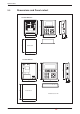
1 Introduction 1.1 General Description . . . . . . . . . . . . . . . . . . . . . . . . . . . . . . . . . . . . . . . . . . . . . . . . .7 1.2 Connections . . . . . . . . . . . . . . . . . . . . . . . . . . . . . . . . . . . . . . . . . . . . . . . . . . . . . . .7 2 Specifications 2.1 General Specifications . . . . . . . . . . . . . . . . . . . . . . . . . . . . . . . . . . . . . . . . . . . . . . .8 2.2 Specifications of the Operating Terminals . . . . . . . . . . . . . . . . . . . . . . . . . .
Safety Information For qualified staff only This manual is only intended for use by properly trained and qualified electrical technicians who are fully acquainted with automation technology safety standards. All work with the hardware described, including system design, installation, setup, maintenance, service and testing, may only be performed by trained electrical technicians with approved qualifications who are fully acquainted with the applicable automation technology safety standards and regulations.
Safety warnings in this manual In this manual special warnings that are important for the proper and safe use of the products are clearly identified as follows: P DANGER: Personnel health and injury warnings. Failure to observe the precautions described here can result in serious health and injury hazards. E CAUTION: Equipment and property damage warnings. Failure to observe the precautions described here can result in serious damage to the equipment or other property.
General safety information and precautions The following safety precautions are intended as a general guideline for using the PLC together with other equipment. These precautions must always be observed in the design, installation and operation of all control systems. P CAUTION: 쎲 Observe all safety and accident prevention regulations applicable to your specific application.
Introduction 1 Introduction This Installation Manual includes a brief summary of the main specifications of the graphic operation terminals F920GOT-BBD5-K-E and F930GOT-BBD-K-E, which should be sufficient to enable experienced users to install and configure the units. For further information on the operation terminals please refer to the manuals of the GOT F900 series. These manuals can be ordered or downloaded free of charge from the Mitsubishi website at "www.mitsubishi-automation.com". 1.
Specifications 2 Specifications 2.1 General Specifications E CAUTION: Please operate the Graphic Operation Terminal in the listed conditions only. If the GOT is used under other conditions, electric shock, fire, malfunction, damages or deterioration may be caused.
Specifications 2.2 Specifications of the Operating Terminals Item F920GOT-BBD5-K-E F930GOT-BBD-K-E Supply voltage 5 V DC (±5%) (supplied from PLC via the data cable) 24 V DC (+10% / –15%), Ripple voltage 200 mV or less Backlight ON 220 mA @ 5 V DC 220 mA @ 24 V DC Backlight OFF 180 mA @ 5 V DC 120 mA @ 24 V DC — Build-in, irreplaceable — 5 ms or less If less than 5 ms, the GOT will continue operation. If 5 ms or more, the GOT will shut down.
Specifications 2.3 Dimensions and Panel-cutout COM0 RS-422 COM1 RS-232C F1 F2 F3 7 8 9 4 5 6 1 2 3 0 - . 90 F4 F5 F6 SET ESC DEV ENT 118 134 F920-GOT-BBD5-K-E 106 5 35,5 119 Panel-cutout 92 183 169 F930-GOT-BBD-K-E COM1 RS-232C COM0 RS-422 24VDC - 154 + 7 8 9 4 5 6 1 2 3 0 - .
Description of the GOTs 3 Description of the GOTs 3.1 F920GOT-BBD5-K-E F2 F3 7 8 9 4 5 6 1 2 3 0 - . F1 COM0 RS-422 COM1 RS-232C Number F4 F6 SET ESC DEV ENT F5 Item Description 쐃 Display Monochrome liquid cristal display (LCD) Slots for mounting brackets Four mounting brackets (two on each side) are used to press the GOT from the backside of the panel against the panel-cutout.
Description of the GOTs 3.2 F930GOT-BBD-K-E COM1 RS-232C COM0 RS-422 24VDC - 쐅 Number + 7 8 9 4 5 6 1 2 3 0 - . SET ESC DEV ENT Item Description 쐃 Display Monochrome liquid cristal display (LCD) with touch-sensitive surface. That means that inputs can be made by touching the screen.
Description of the GOTs 3.2.1 Labeling the Function Keys The function keys of the F930GOT-K can be labeled to suit the application. Insert the label from the rear of the GOT: Label Labeling of the function keys 143 8 23 8 23 8 23 6 2 23 5 10 30 Label dimensions (Unit: mm) 10 Insertion direction 3.2.
Installation 4 Installation The operation terminals of the GOT F900 series are designed to be mounted in a control panel or the door of a control cabinet. All mounting angles from 0쎷 (horizontal, e. g. in an control panel) to 90쎷 (vertical, e. g. in a door) are allowed, but the ambient temperature must kept below 50 쎷C. 90° GOT Display 0° Control panel etc. 4.1 Preparing the Panel Surface Cut a rectangular mounting hole in the panel surface with the dimensions shown on page 10. A space of approx.
Installation 4.2 Mounting The GOT is fixed in the panel with the mounting brackets (four for the F920GOT-K, six for the F930GOT-K) delivered with the operation panel. Because no holes are needed for these fixings, they are invisible from the front. 햲 Attach the packing seal to the backside of the GOT. 햳 Insert the GOT from the front of the panel into the cutout. 7 8 9 4 5 6 1 2 3 0 - . SET ESC DEV ENT 햴 Hang the hook of the mounting brackets into the slots on the sides of the GOT.
Wiring 5 Wiring 5.1 Connection with the PLC 5.1.1 F920GOT-BBD5-K-E E CAUTION: Do not connect a PLC to the RS422 port and at the same time a second PLC to the RS232C port of the GOT. Doing so can damage the GOT or the PLCs. Connection to a CPU of the FX0, FX0S, FX0N, FX1S, FX1N, FX2N or FX2NC series, or the interface adapters FX1N-422-BD and FX2N-422-BD: F920GOT-K side Port Connector RS422 9-pin D-SUB, male Cable Length PLC side FX-50DU-CAB0 3.
Wiring Connection to a CPU of the MELSEC System Q The RS232C port of the GOT is used to connect a F920GOT-K with the programming port of a Q series CPU: F920GOT-K side Port Cable Connector Prepared by the user 9-pin D-SUB, female PIN (cross section 0.08 mm2 or more) RS232C PLC side (Q series) Length max. 3.0 m PIN 6-pin MINI-DIN Shielding to the hood of the connectors 5 1 9 2 2 3 1 4 5 5 3 6 6 3 5 1 2 6 6 4 7 8 9 4 When a personal computer (e.g.
Wiring 5.1.2 F930GOT-BBD-K-E Connection to a CPU of the FX0, FX0S, FX0N, FX1S, FX1N, FX2N or FX2NC series, or the interface adapters FX1N-422-BD and FX2N-422-BD: F930GOT-K side Port Connector RS422 9-pin D-SUB, male Cable Length PLC-Side FX-50DU-CAB0/EN 3.0 m 8-pin MINI-DIN Connection to an active data interface module FX0N-232ADP A communication adapter FX1N-CNV-BD or FX2N-CNV-BD is required in addition.
Wiring Connection to the programming port of a A or QnA series CPU F930GOT-K side Port Connector RS422 9-pin D-SUB, male Cable Length FX-40DU-CAB/EN 3.0 m Verbindung zur SPS 25-pin D-SUB, male Connection to the interface modules AJ71UC24, AJ71QC24N, A1SJ71UC24-R4, A1SJ71QC24, and QJ71C24 F930GOT-K side Port Connector RS422 9-pin D-SUB, male PIN Cable Length Prepared by the user max.
Wiring Connection to the interface modules AJ71C21-S1, AJ71UC24, AJ71UC24-S2, AJ71QC24N-R2, and AJ71QC24N F930GOT-K side Port Connector RS232C 9-pin D-SUB, male PIN Cable Length Prepared by the user max.
Wiring 5.2 Connection to a Personal Computer For the transfer of the user screens to the operation terminal, connect a PC or a notebook computer (with the required software installed) to the RS232C port of the GOT. Anschluss am F920GOT/F930GOT 5.3 Port Connector RS232C 9-pin D-SUB, female Cable Length PC side FX-232-CAB1 3.0 m 9-pin D-SUB, female Wiring of the Power Supply (F930GOT-K) 2 Please use wires with a cross section of at least 0,75 mm for the power supply .
Start Up 6 Start Up 햲 Make all connection required as shown in chapter 5. 햳 Turn on the power of the GOT. 햴 Check the display. On the system screen „SET-UP MODE“ you can adjust the brightness of the screen („LCD CONTRAST“). 햵 Set the required mode and the type of the connected PLC on the „SET-UP MODE“ screen. If this setting is not correct, communication between GOT and PLC is not possible. 햶 Transfer the user screens to the GOT. NOTE 6.
Maintenance 7 Maintenance P 7.1 DANGER: Always switch off the power supply of the GOT before starting the replacement of the battery. Replacement of the battery (F930GOT-K only) When the voltage of the battery drops, an interface device (system information) in the connected PLC turns on. The device is allocated by the screen design software. Check this device in the program of the PLC und use it for instance to control a lamp so that the voltage drop can be monitored outside the GOT.
MITSUBISHI ELECTRIC HEADQUARTERS EUROPEAN REPRESENTATIVES EUROPEAN REPRESENTATIVES EURASIAN REPRESENTATIVES MITSUBISHI ELECTRIC EUROPE EUROPE B.V. German Branch Gothaer Straße 8 D-40880 Ratingen Phone: +49 (0) 2102 / 486-0 Fax: +49 (0) 2102 / 486-1120 e mail: megfamail@meg.mee.com MITSUBISHI ELECTRIC FRANCE EUROPE B.V. French Branch 25, Boulevard des Bouvets F-92741 Nanterre Cedex Phone: +33 1 55 68 55 68 Fax: +33 1 55 68 56 85 e mail: factory.automation@fra.mee.com MITSUBISHI ELECTRIC IRELAND EUROPE B.