MITSUBISHI ELECTRIC AUTOMATION, INC UNINTERRUPTIBLE POWER SUPPLY SYSTEM 9800A SERIES OWNERS / TECHNICAL MANUAL (For parallel operation possible model only.) Revision 2.03 Apr.
MITSUBISHI ELECTRIC 9800A SERIES UPS OWNERS / TECHNICAL MANUAL Preface MITSUBISHI ELECTRIC 9800A SERIES UPS Page Number: i
MITSUBISHI ELECTRIC 9800A SERIES UPS OWNERS / TECHNICAL MANUAL Page Number: ii TABLE OF CONTENTS LIST OF TABLES ................................................................................................ iii LIST OF FIGURES .............................................................................................. iv HOW TO USE THIS MANUAL ............................................................................ v 1.0 INTRODUCTION ...............................................................
MITSUBISHI ELECTRIC 9800A SERIES UPS OWNERS / TECHNICAL MANUAL Page Number: iii List of Tables Table 1.1 Power Specifications..................................................................... 1-13 Table 1.2 UPS Module Information............................................................... 1-13 Table 1.3 Detail of Specifications ................................................................. 1-13 Table 1.4 Rating of Contactor and Fuses.....................................................
MITSUBISHI ELECTRIC 9800A SERIES UPS OWNERS / TECHNICAL MANUAL Page Number: iv List of Figures Figure 1.1 Single Line Diagram-Normal Operation.................................................... 1-5 Figure 1.2 Single Line Diagram-Bypass Operation ................................................... 1-6 Figure 1.3 Single Line Diagram-Battery Operation.................................................... 1-7 Figure 1.4 UPS Parts Location.................................................................
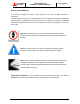
MITSUBISHI ELECTRIC 9800A SERIES UPS OWNERS / TECHNICAL MANUAL Page Number: v How to use this Manual This manual is designed for ease of use, giving the user easy and quick reference to information. This manual uses notice icons to draw attention to the user important information regarding the safe operation and installation of the UPS. The notice icons used in this manual are explained below, and should be taken into account and adhered to whenever they appear in the text of this manual.
MITSUBISHI ELECTRIC 9800A SERIES UPS OWNERS / TECHNICAL MANUAL Page Number: 1-1 1.0 INTRODUCTION Your Mitsubishi Uninterruptible Power System (UPS) is designed to provide many years of reliable protection from power failure, brown-outs, line noise, and voltage transients. To ensure optimum performance of the equipment, follow the manufacturer's instructions. This manual contains descriptions required to operate the UPS. Please read this manual carefully and retain it for future reference.
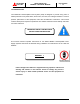
MITSUBISHI ELECTRIC Page Number: 1-2 9800A SERIES UPS OWNERS / TECHNICAL MANUAL WARNING 2 This UPS does not include a Bypass input circuit breaker (MCCB) to protect bypass circuit. The Bypass input circuit breaker (MCCB) is to be field supplied and installed.
MITSUBISHI ELECTRIC 9800A SERIES UPS OWNERS / TECHNICAL MANUAL Page Number: 1-3 1.1 GENERAL The Mitsubishi 9800A SERIES UPS is designed to provide continuous and clean electrical power to a critical load. Additionally the UPS monitors power conditions affecting the load. In the event of an input power failure, the UPS will supply power to the critical load for the specified battery time.
MITSUBISHI ELECTRIC 9800A SERIES UPS OWNERS / TECHNICAL MANUAL Page Number: 1-4 1.2 Definitions UNINTERRUPTIBLE POWER SUPPLY SYSTEM (UPS) - All components within the UPS Module Cabinet and associated batteries that function as a system to provide continuous, conditioned AC power to a load. This is sometimes referred to as the "System".
MITSUBISHI ELECTRIC Page Number: 1-5 9800A SERIES UPS OWNERS / TECHNICAL MANUAL 1.3 Overview The UPS provides two power paths between the utility source and the critical load. Figure 1.1 shows the path for normal operation, with the load powered from the inverter. Figure 1.2 shows the path for bypass operation, with the load supplied through the static bypass line. A) Normal operation: Load power supplied by each system UPS inverter. Figure 1.
MITSUBISHI ELECTRIC Page Number: 1-6 9800A SERIES UPS OWNERS / TECHNICAL MANUAL The Bypass Input circuit breaker (MCCB) for protection of the UPS and cables are field supplied and field installed. (See WARNING 2 on page 1-2) B) Bypass Operation: Load Power supplied through each system UPS internal static bypass line. FIGURE 1.2 Single Line Diagram - Bypass Operation: Load fed through Internal static bypass line.
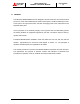
MITSUBISHI ELECTRIC Page Number: 1-7 9800A SERIES UPS OWNERS / TECHNICAL MANUAL C) Battery operation: Load Power supplied by each system UPS battery and inverter. FIGURE 1.3 Single Line Diagram - Battery Operation CB AC Bypass Input Static Transfer Switch CB3 User supplied MCCB RECTIFIER INVERTER 52S AC input Output CB1 52C Power Flow CB2 Not in Use Battery cabinet UPS Module Referring to Figure 1.
MITSUBISHI ELECTRIC FIGURE 1.4-a Page Number: 1-8 9800A SERIES UPS OWNERS / TECHNICAL MANUAL UPS Parts Location (100kVA, 150kVA, 225kVA) UPS module FRONT VIEW Inverter Chopper unit AC capacitors DC capacitors Rectifier unit 1. CPM 52S CB3 CB1 3. External I/F circuit PCB IOAU-04 2. Grounding Bar 52C FIGURE 1.4-b UPS Parts Location (300kVA,375kVA) 2. Grounding Bar UPS module FRONT VIEW 52S 52C 3. External I/F circuit PCB IOAU-04 CB1 CB3 1.
MITSUBISHI ELECTRIC FIGURE 1.4-c 9800A SERIES UPS OWNERS / TECHNICAL MANUAL Page Number: 1-9 UPS Parts Location (500kVA) UPS module FRONT VIEW 3. External I/F circuit PCB IOAU-04 1. CPM 52S 2.
MITSUBISHI ELECTRIC FIGURE 1.4-d 9800A SERIES UPS OWNERS / TECHNICAL MANUAL Page Number: 1-10 UPS Parts Location (750kVA) UPS module FRONT VIEW 3. External I/F circuit PCB IOAU-04 AC capacitors 2. Grounding Bar 52C 52S CB1 1.
MITSUBISHI ELECTRIC Page Number: 1-11 9800A SERIES UPS OWNERS / TECHNICAL MANUAL FIGURE 1.5 UPS Parts Location (Continued) UPS module REAR OF FRONT DOOR (Right side) SYNC.LED 5 INVERTER START | FIGURE 1.6 6 INVERTER STOP | | FAULT RESET | MAINTENANCE SWITCH | TEST SWITCH | BOOT SWITCH 7 8 9 10 External I/F circuit PCB IOAU-04 3. External contact signal terminal IOAU-04 4.
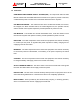
MITSUBISHI ELECTRIC 9800A SERIES UPS OWNERS / TECHNICAL MANUAL Page Number: 1-12 Description of Figures 1.4, 1.5, and 1.6: 1. CPM - Circuit protector for control power supply. 2. Grounding bar (G) 3. External contact signal terminal block (FIGURE 1.6) - Terminal block to connect contact signal input/output lines to and from the external devices. Refer to Figure 2.15 section 2.4 for details. 4. RS232C communication connector (FIGURE 1.6) - Refer to Figure 2.18 section 2.5 for details. 5.
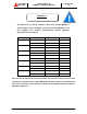
MITSUBISHI ELECTRIC Page Number: 1-13 9800A SERIES UPS OWNERS / TECHNICAL MANUAL 1.4 Specifications The UPS name plate displays the rated kVA as well as nominal voltages and currents. The name plate is located on the inside of the UPS front door. TABLE 1.
MITSUBISHI ELECTRIC Page Number: 1-14 9800A SERIES UPS OWNERS / TECHNICAL MANUAL TABLE 1.3 Detail of Specifications Rated Output kVA Rated Output kW 100 80 Configuration Voltage Frequency Reflected Current THD 150 120 225 180 AC INPUT 375 338 500 450 3 phase, 3 wire 277/480 V, 346/600 V +15% to -15% 60 Hz +/-5% 6% max. at 100% load; 9% max.
Page Number: 1-15 9800A SERIES UPS OWNERS / TECHNICAL MANUAL MITSUBISHI ELECTRIC TABLE 1.
MITSUBISHI ELECTRIC Page Number: 2-1 9800A SERIES UPS OWNERS / TECHNICAL MANUAL 2.0 OPERATOR CONTROLS AND INDICATORS The 9800A Series operator controls and indicators are located as follows: Circuit breakers and contactors: Inside the module UPS status indicators: Outside of front door FIGURE 2.1 Operation/Display Panel (Front panel) 3 4 2 5 1 6 LOAD ON INVERTER BATTERY OP. LOAD ON BYPASS OVER LOAD LCD FAULT UPS FAULT 540V EMRG.
MITSUBISHI ELECTRIC 9800A SERIES UPS OWNERS / TECHNICAL MANUAL Page Number: 2-2 2.1 LED Display 1) Load on inverter [ LOAD ON INVERTER ](green) Illuminates when power is supplied from inverter to the critical load. (Indicates the state of inverter transfer switch "52C".) 2) Battery operation [ BATTERY OP. ](yellow) Illuminates when power is supplied from batteries following a power failure. 3) Load on bypass [ LOAD ON BYPASS ](green) Illuminates when power is supplied to load devices by static bypass.
MITSUBISHI ELECTRIC 9800A SERIES UPS OWNERS / TECHNICAL MANUAL Page Number: 2-3 2.3 Liquid Crystal Display (8) The Liquid Crystal Display (LCD) panel indicates power flow, measured values, operational guidance, data records and error messages. The LCD panel has a back-light which facilitates viewing in different ambient lighting conditions. The LCD will automatically clear and turn off, if the screen is not activated within 3 minute period. The LCD is turned back on when it is touched again.
MITSUBISHI ELECTRIC 9800A SERIES UPS OWNERS / TECHNICAL MANUAL Page Number: 2-4 FIGURE 2.3 Start/Stop screen FIGURE 2.4 PIN protection screen FIGURE 2.5 Bypass voltage abnormal message screen B) MEASUREMENT MENU (FIGURE 2.6) This screen shows details of measured values. Bypass voltage, input voltage, output line to line voltage and output frequency are displayed. Output currents are displayed as RMS values. FIGURE 2.
MITSUBISHI ELECTRIC 9800A SERIES UPS OWNERS / TECHNICAL MANUAL Page Number: 2-5 C) SETUP MENU (FIGURE 2.7) This screen prompts the user to select: (a) whether the start & stop operation will be performed by local or remote operation; (b) date & time adjustment; (c) battery equalizing charge. The battery equalizing charge operation key will appear when battery equalizing charge is set up (Setup is based on battery type). FIGURE 2.7 Setup screen D) LOG MENU (FIGURE 2.
MITSUBISHI ELECTRIC Page Number: 2-6 9800A SERIES UPS OWNERS / TECHNICAL MANUAL 2.) Battery log (FIGURE 2.10) This screen displays the cumulative battery discharging record. FIGURE 2.10 Battery log screen 2.3.2 INPUT POWER FAILURE During an Input Power Failure, the UPS inverter will be powered by the UPS batteries. The following will be displayed on the main and measurement screen (Indication of battery operation and remaining battery life). FIGURE 2.11 Main screen (Battery operation) 480V FIGURE 2.
MITSUBISHI ELECTRIC 9800A SERIES UPS OWNERS / TECHNICAL MANUAL Page Number: 2-7 2.3.3 FAULT INDICATION (FIGURE 2.13) “MESSAGE” and “SILENCE ALARM” buttons will appear on the main menu when UPS failure condition has occurred. FIGURE 2.13 Main screen (Fault indication) 540V The following will be displayed when the message key on the LCD panel is pressed. 1) Message (FIGURE 2.14) The display shows a fault code, the description of the fault and a guidance of what action is to be taken by the user.
MITSUBISHI ELECTRIC 9800A SERIES UPS OWNERS / TECHNICAL MANUAL Page Number: 2-8 2.4 External Signal Terminal Block The UPS is equipped with a series of input/output terminals for external annunciation of alarms and for remote access of certain UPS functions. The layout of terminals is shown in Figure 2.15. with a functional description of the input/output port presented. OUT1 to OUT6 are user programmable, but are factory default set being also shown in Figure 2.15. FIGURE 2.
MITSUBISHI ELECTRIC 9800A SERIES UPS OWNERS / TECHNICAL MANUAL Page Number: 2-9 FIGURE 2.15-2 External Signal Terminal Block (NEC Class2) TN2 2 4 6 8 10 12 14 16 18 20 22 24 26 28 30 1 3 5 7 9 11 13 15 17 19 21 23 25 IN1: REMOTE INVERTER START IN2: REMOTE INVERTER STOP IN3: BATTERY TEMP.
MITSUBISHI ELECTRIC Page Number: 2-10 9800A SERIES UPS OWNERS / TECHNICAL MANUAL A) Output Contacts (for external alarm annunciation) Output contacts consist of form “A” dry type contacts. Rated capacity of all output contacts is NEC Class2 (30Vdc/1Adc). All dry contacts should be operated at their rated values or lower. Figure 2.16 illustrates a typical installation. The external relay can also be a lamp, LED, computer, etc. FIGURE 2.
MITSUBISHI ELECTRIC NOTE: Page Number: 2-11 9800A SERIES UPS OWNERS / TECHNICAL MANUAL The UPS is equipped with a selectable output contact feature. The above alarms are the default settings. Contact MITSUBISHI ELECTRIC AUTOMATION, INC. for setup information. B) Input Contacts (for remote access of UPS) External contacts are provided by the user of the UPS system. Terminal voltage at the UPS is 24Vdc. Provide external dry contact accordingly.
MITSUBISHI ELECTRIC Page Number: 2-12 9800A SERIES UPS OWNERS / TECHNICAL MANUAL Terminals 7 to 8 "Power Demand Command" contact input (IN4) This contact is used to control the input power. Power demand is turned ON when the contact is closed, and power demand is turned OFF when the contact is open. Terminals 9 to 18 "Spare" contact input (IN5 through IN9) Terminals 19 to 20 "Remote EPO" contact input Used to perform a remote UPS Emergency Power Off (EPO). The load will be dropped.
MITSUBISHI ELECTRIC Page Number: 3-1 9800A SERIES UPS OWNERS / TECHNICAL MANUAL 3.0 INSTALLATION AND OPERATION 3.1 Transportation and Installation TABLE 3.1 How to transport and install the system Transportation Installation Transport unit with forklift. Carry with overhead Using the pre drilled holes (4 - 24) in the crane using UPS channel base, anchor the unit using eyebolts provided. appropriate hardware. (Not provided) Note : Do not transport in a horizontal position.
MITSUBISHI ELECTRIC Page Number: 3-2 9800A SERIES UPS OWNERS / TECHNICAL MANUAL D) External Battery Supply Please refer to the following when installing and maintaining batteries: 1. The customer shall refer to the battery manufacturer's installation manual for battery installation and maintenance instructions. 2. The maximum permitted fault current from the remote battery supply, and the DC voltage rating of the battery supply over-current protective device are shown in Table 3.3. TABLE 3.
MITSUBISHI ELECTRIC 9800A SERIES UPS OWNERS / TECHNICAL MANUAL Page Number: 3-3 b.) DC Input to UPS 3. 1. Positive cable to BP bus bar in UPS rectifier section. 2. Negative cable to BN bus bar in UPS rectifier section. Connect the grounding conductor from the input service entrance to the UPS ground bar. 4. Two (2) sources feeding the UPS: (1) Connect the rectifier input power cables from the input service entrance to the rectifier input power terminals, identified as A, B, C in Figures 3.2-a~g.
MITSUBISHI ELECTRIC 9800A SERIES UPS OWNERS / TECHNICAL MANUAL Page Number: 3-4 (3) Connect the external signal terminal block as desired. Refer to section 2.4 and Figure 2.15 for functional description. 2mm2, or less, shielded conductor is recommended. NOTES: 1. Confirm that all UPS internal contactors (breakers) "CB1", "CB2", and "CB3" are open before energizing UPS. 2. UPS power terminals are supplied with stud type fittings.
9800A SERIES UPS OWNERS / TECHNICAL MANUAL MITSUBISHI ELECTRIC Page Number: 3-5 TABLE 3.4 Recommended Cable Sizes kVA Capacity 100kVA 150kVA 225kVA 300kVA 375kVA 500kVA 750kVA Input Voltage 480V Output Voltage 480V 600V 600V 480V 480V 600V 600V 480V 480V 600V 600V 480V 480V 600V 600V 480V 480V 600V 600V 480V 480V 600V 600V 480V 480V 600V 600V Input Side * 1, 2 Cable Torque Size in. lbs 1 AWG 100 - 135 or larger in. lbs 2 AWG 100 - 135 or larger in.
MITSUBISHI ELECTRIC Page Number: 3-6 9800A SERIES UPS OWNERS / TECHNICAL MANUAL TABLE 3.5 Crimp Type Compression Lug WIRE SIZE (CODE) WIRE STRAND CLASS 1 B 1/0 I B 2/0 I B 3/0 I B 4/0 I B 250 MCM I B 300 MCM I B 350 MCM I B 400 MCM I B 500 MCM I B I NOTE: RECOMMENDATION VENDOR CAT. NO.
Page Number: 3-7 9800A SERIES UPS OWNERS / TECHNICAL MANUAL MITSUBISHI ELECTRIC FIGURE 3.2-a-1 Diagram of input/output bus bars and terminal blocks (100kVA, 150kVA, 225kVA UPS, Input voltage 480Vac) Location of bus bars and terminal blocks Detailed Terminals H=79.7” (2025mm) 100kVA : 43.3” (1100mm) 150kVA : 47.2” (1200mm) 225kVA : 55.1” (1400mm) For power terminals, use 5/16” (8mm) Diameter bolts. D=29.
Page Number: 3-8 9800A SERIES UPS OWNERS / TECHNICAL MANUAL MITSUBISHI ELECTRIC FIGURE 3.
Page Number: 3-9 9800A SERIES UPS OWNERS / TECHNICAL MANUAL MITSUBISHI ELECTRIC FIGURE 3.2-b-1 Diagram of input/output bus bars and terminal blocks (100kVA, 150kVA, 225kVA UPS, Input voltage 600Vac) Location of bus bars and terminal blocks Detailed Terminals H=79.7” (2025mm) 100kVA : 73.3” (2014mm) 150kVA : 79.2” (2113mm) 225kVA : 99.1” (2520mm) Input cabinet D=29.9” (760mm) Input cabinet UPS module AC Input H1,H2,H3 Battery Input BN,BP For power terminals, use 5/16” (8mm) Diameter bolts.
9800A SERIES UPS OWNERS / TECHNICAL MANUAL MITSUBISHI ELECTRIC Page Number: 3-10 FIGURE 3.
MITSUBISHI ELECTRIC FIGURE 3.2-c-1 Page Number: 3-11 9800A SERIES UPS OWNERS / TECHNICAL MANUAL Diagram of input/output bus bars and terminal blocks (300kVA, 375kVA UPS, Input voltage 480Vac) Location of bus bars and terminal blocks Detailed Terminals H=79.7” (2025mm) D=37.8” (960mm) 76.
Page Number: 3-12 9800A SERIES UPS OWNERS / TECHNICAL MANUAL MITSUBISHI ELECTRIC FIGURE 3.
Page Number: 3-13 9800A SERIES UPS OWNERS / TECHNICAL MANUAL MITSUBISHI ELECTRIC FIGURE 3.2-d-1 Diagram of input/output bus bars and terminal blocks (300kVA, 375kVA UPS, Input voltage 600Vac) Location of bus bars and terminal blocks Detailed Terminals H=79.7” (2025mm) D=37.8” (960mm) DC Input Bypass Input BN A40 B40 C40 BP AC Output N50 300kVA : 120.8” (3068mm) 375kVA : 130.
MITSUBISHI ELECTRIC 9800A SERIES UPS OWNERS / TECHNICAL MANUAL Page Number: 3-14 FIGURE 3.
FIGURE 3.2-e-1 Page Number: 3-15 9800A SERIES UPS OWNERS / TECHNICAL MANUAL MITSUBISHI ELECTRIC Diagram of input/output bus bars and terminal blocks (500kVA, 750kVA UPS, Input voltage 480Vac) Location of bus bars and terminal blocks Detailed Terminals H=79.7” (2025mm) D=37.8" (960mm) 51.2” (1300mm) N40 63.
MITSUBISHI ELECTRIC Page Number: 3-16 9800A SERIES UPS OWNERS / TECHNICAL MANUAL FIGURE 3.
Page Number: 3-17 9800A SERIES UPS OWNERS / TECHNICAL MANUAL MITSUBISHI ELECTRIC FIGURE 3.2-f-1 Diagram of input/output bus bars and terminal blocks (500kVA, 750kVA UPS, Input voltage 600Vac) Location of bus bars and terminal blocks Detailed Terminals H=79.7” (2025mm) D=37.8" (960mm) 168.
9800A SERIES UPS OWNERS / TECHNICAL MANUAL MITSUBISHI ELECTRIC Page Number: 3-18 FIGURE 3.
MITSUBISHI ELECTRIC Page Number: 3-19 9800A SERIES UPS OWNERS / TECHNICAL MANUAL FIGURE 3.
MITSUBISHI ELECTRIC 9800A SERIES UPS OWNERS / TECHNICAL MANUAL Page Number: 3-20 FIGURE 3.
MITSUBISHI ELECTRIC Page Number: 3-21 9800A SERIES UPS OWNERS / TECHNICAL MANUAL CRITICAL LOAD CABINET FIGURE 3.
MITSUBISHI ELECTRIC Page Number: 3-22 9800A SERIES UPS OWNERS / TECHNICAL MANUAL FIGURE 3.
MITSUBISHI ELECTRIC 9800A SERIES UPS OWNERS / TECHNICAL MANUAL Page Number: 3-23 FIGURE 3.4-c Diagram of Power Wire & Control Wire Connect ( Parallel connection ) Critical Load Cabinet AC Output UPS-1 UPS-1 A UPS-n*1 UPS-2 B 25 25 26 26 25 IOAU-04 TN2 IOAU-04 TN2 26 IOAU-04 TN2 *2 C N UPS-2 TB1 35 36 37 38 . .
9800A SERIES UPS OWNERS / TECHNICAL MANUAL MITSUBISHI ELECTRIC 3.4 Page Number: 3-24 Operating Procedures For MMS, Refer section “D) MMS Start-up Procedure”. A) Start-up Procedure a.) Verify that the External Bypass Input Circuit Breaker for each unit is closed (Breaker is user supplied.) b.) If a dual source is feeding the UPS, close the External AC Rectifier Input Circuit Breaker manually (user supplied). Start-up of UPS 1. Verify that Control Circuit Breakers (CPM) is closed.
MITSUBISHI ELECTRIC 9800A SERIES UPS OWNERS / TECHNICAL MANUAL Page Number: 3-25 B) Shut-down Procedure If a total UPS shutdown is required, verify that the critical load is OFF. Shut-down of UPS 1. Press the "START/STOP MENU" from the Main Menu on the LCD. Note: When "REMOTE OPERATION MODE" is displayed on the LCD panel, the inverter stop operation can only be performed remotely. If local inverter stop operation is required (at the UPS), select "LOCAL" in "Remote/Local" selection in setup page.
MITSUBISHI ELECTRIC C) 9800A SERIES UPS OWNERS / TECHNICAL MANUAL Page Number: 3-26 Bypass Operation Procedure UPS 1. Check for “SYNC” on the LCD. 2. Press the "START/STOP MENU" from the LCD Main Menu. 3. Press the "STOP" key on the LCD. ** Transfer from bypass to inverter. UPS 1. Press the "START/STOP MENU" from the LCD Main Menu. 2. Press the "START" key on the LCD. Note: When "REMOTE OPERATION MODE" is displayed on the LCD panel, the inverter start or stop operation can only be performed remotely.
MITSUBISHI ELECTRIC 9800A SERIES UPS OWNERS / TECHNICAL MANUAL Page Number: 3-27 D) MMS Start-up Procedure a) Verify that Critical Load Cabinet (CLC) Circuit Breaker SMB is closed. b) Verify that CLC System Output Circuit Breaker 52L is open c) Verify that CLC UPS Circuit Breakers 52L1, 52L2…and 52Ln are closed. Start-up of UPS-1 1. Verify that Control Circuit Breakers (CPM) is closed. (When Inverter is stopped, the Control Circuit Breaker is not normally opened) 2.
MITSUBISHI ELECTRIC 9800A SERIES UPS OWNERS / TECHNICAL MANUAL Page Number: 4-1 4.0 RESPONSE TO UPS FAILURE UPS FAULT Annunciator Silence Depress “SILENCE ALARM” key on MAIN menu. Recording of Fault Refer to the list of fault codes in section 6.0 for error description. Take necessary action according to display guidance. Primary Action Information to Service Center When a faults occur, contact the Authorized Mitsubishi Service Representative or call Mitsubishi at 1-800-887-7830.
MITSUBISHI ELECTRIC 9800A SERIES UPS OWNERS / TECHNICAL MANUAL Page Number: 5-1 5.0 PARTS REPLACEMENT Contact Mitsubishi or its Authorized Service Center on all issues regarding the replacement of parts. A) Battery Battery lifetime may vary according to the frequency of use and the average ambient operating temperature. The end of battery life is defined as the state of charge resulting in an ampere-hour capacity less than, or equal to, 80% of nominal capacity.
MITSUBISHI ELECTRIC 9800A SERIES UPS OWNERS / TECHNICAL MANUAL Page Number: 6-1 6.0 FAULT CODES This section covers fault codes, their description and required action. At time of error : A) Verify and record the occurrence of the alarm. Note details of alarm message displayed on the LCD display panel. Contact Mitsubishi Electric Automation, Inc. at 1-800-887-7830. B) If a circuit breaker (MCCB) has tripped, depress the toggle to reset the breaker before closing it again.
MITSUBISHI ELECTRIC Failure 9800A SERIES UPS OWNERS / TECHNICAL MANUAL Page Number: 6-2 Table 6.
MITSUBISHI ELECTRIC 9800A SERIES UPS OWNERS / TECHNICAL MANUAL CALL SERVICE UF166 IGBT FAULT (A) IGBT module (A) overcurrent UF167 IGBT FAULT (B) IGBT module (B) overcurrent UF168 IGBT FAULT (C) IGBT module (C) overcurrent INVERTER Output overvoltage during inverter CALL SERVICE OVERVOLTAGE power supply (+ 15%) INVERTER Output low voltage during inverter CALL SERVICE UNDERVOLTAGE supply (-15%) UF201 UF202 UF203 UP204 INVERTER OUTPUT CIRCUIT ABNORMAL 52C not turned ON UF210 52C AB
MITSUBISHI ELECTRIC UF305 UF306 UF309 UF352 UPS CONTROL CIRCUIT ERROR CALL SERVICE Control clock abnormality ENGINEER UPS CONTROL CIRCUIT Control power source circuit CALL SERVICE ERROR abnormality ENGINEER INVERTER VOLTAGE Inverter output voltage abnormality CALL SERVICE ABNORMAL before inverter power supply CONTROL POWER SUPPLY ABNORMAL UF402 52S ABNORMAL UF403 CB3 ABNORMAL UF451 52S ABNORMAL ENGINEER CALL SERVICE Control circuit abnormality ENGINEER 52S not turned OFF, or 52S t
MITSUBISHI ELECTRIC UA817 UA819 UA820 UA824 UA831 UA834 UA841 UA842 Page Number: 6-5 9800A SERIES UPS OWNERS / TECHNICAL MANUAL EMERGENCY STOP ACTIVATED Emergency stop applied - - Alarm - [1] Alarm - [1] Alarm - TURN ON CB2 [1] Alarm - - [1] Alarm - - - Alarm - - - Alarm - - - Alarm - REMOTE START There is an error with the remote CALL SERVICE BUTTON ABNORMAL start switch.
MITSUBISHI ELECTRIC 9800A SERIES UPS OWNERS / TECHNICAL MANUAL Page Number: 6-6 (Note 1) Audible annunciator: [1] intermittent sound, [2] continuous sound. (Note 2) 1) "Major" is defined as major failure. Inverter transferred to the static bypass line; 2) "Minor" is defined as a minor failure. UPS continues to operate normally, but cause of alarm must be identified; (Note 3) Indicates one of two possible LED illumination patterns - continuously on (lit) or intermittent (flicker).
MITSUBISHI ELECTRIC 9800A SERIES UPS OWNERS / TECHNICAL MANUAL Page Number: 7-1 7.0 Warranty & Out of warranty Service The Mitsubishi Electric UPS Systems Group Service Department has many Authorized Service Centers place strategically throughout the US, Canada and Latin America. For both in warranty and out of warranty service, please contact Mitsubishi Electric Automation, Inc. at (847) 478-2500.
Page Number: 7-2 9800A SERIES UPS OWNERS / TECHNICAL MANUAL MITSUBISHI ELECTRIC Mitsubishi Electric Automation, Inc. UNINTERRUPTIBLE POWER SUPPLIES 500 Corporate Woods Parkway, Vernon Hills, IL 60061 Phone: (847) 478-2643, Fax: (847) 478-2290 UPS Warranty Registration __ Register UPS for Warranty __ Address Change To validate the Warranty on your UPS this form must be filled out completely by Customer and returned.