
User`s manual


8.3 Wiring Precautions the Part which Matches the EMC Directives
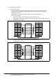
8.3.2 Grounding the ground cable
8 - 16
1
OVERVIEW
2
SYSTEM
CONFIGURATION
3
PERFORMANCE
4
NAMES OF
THE PARTS AND
THEIR SETTINGS
5
ROUGH
PRE-OPERATION
PROCEDURE
6
HANDLING
7
MAINTENANCE AND
INSPECTION
8
EMC DIRECTIVE
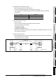
2) Precautions for manufacturing cable
• Make a twisted pair for each signal and SG.
• Connect the braided shield to the connector shell (both ends).
• The cable used for the Mitsubishi EMC Directive compatibility test had the following
specifications.
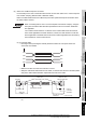
3) Connector (connector cover)
• GOT connector
Use the connector matching the following model for the GOT.
9-pin D-sub (male) inch screw type
manufactured by DDK
17JE-23090-27 (D3CC)
• Connector of computer link unit
Refer to the user’s manual of the serial communication, computer link module or PLC CPU
with computer link function.
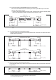
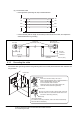
4) Cable production method
• Peel the sheath (with the length shown below) at both ends of the cable, and expose the
shield braided wire for grounding.
• The cable must be 15m or shorter.
Item Specification
Cable type Twisted pair shield cable
Conductor section area (mm
2
)
0.2
130
(5.12)
130
(5.12)
GOT side
Within 230
(9.06)
Within 400
(15.75)
40
(1.57)
Unit: mm (inch)
Ferrite core
(ZCAT3035-1330)
Computer link module side
40
(1.57)