
User`s manual


8 - 17
8.3 Wiring Precautions the Part which Matches the EMC Directives
8.3.2 Grounding the ground cable
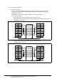
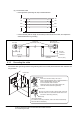
(b) For RS-422 cable (AC30/100/300R4-25P, User created cable)
Refer to the GOT-A900 series User’s Manual (Connection System Manual) for information
about the cable creation method.
• Wrap the cable shield material around the cable, so that the back aluminum foil side (shield
side) of the cable shield material is exposed at both ends of the cable.
*1 The back aluminum foil side of the cable shield material (shield side) should be exposed. (Refer to Section 8.3.2 (1)
(b))
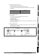
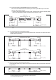
(4) CC-Link Connection (CC-Link dedicated cable)
• Peel the sheath (with the length shown below) at both ends of the cable, and expose the shield
braided wire for grounding.
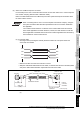
(5) Ethernet Connection (Twisted pair shield cable)
Peel the sheath (with the length shown below) at both ends of the cable, and expose the shield wire
for grounding.
130
(5.12)
130
(5.12)
GOT side
Within 230
(9.84)
Within 400
(15.75)
Ferrite core
(ZCAT3035-1330)
Cable shield material*1
Unit: mm (inch)
PLC CPU side
130
(5.12)
130
(5.12)
GOT side
Within 230
(9.06)
Within 400
(15.75)
40
(1.57)
40
(1.57)
Ferrite core
(ZCAT3035-1330)
Unit: mm (inch)
PLC side
130
(5.12)
130
(5.12)
GOT side
GOT side
Within 230
(9.06)
Within 230
(9.06)
40
(1.57)
40
(1.57)
Unit: mm (inch)
Ferrite core
(ZCAT3035-1330)
GOT side Ethernet module side
Unit: mm (inch)
Within 400
(15.75)
40
(1.57)
Within 23
(9.06)
40
(1.57)