A8GT-50KBF External I/O Interface Module User’s Manual (Hardware) Thank you for choosing the MELSEC-GOT Series. To ensure correct use of this equipment, please read this manual carefully before operating it.
! SAFETY PRECAUTIONS ! (Always read before starting use) When using Mitsubishi equipment, thoroughly read this manual and the associated manuals introduced in the manual. Also pay careful attention to safety and handle the module properly. These precautions apply only to the installation of Mitsubishi equipment and the wiring with the external device. Refer to the user’s manual of the CPU module to be used for a description of the PLC system safety precautions.
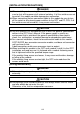
[INSTALLATION PRECAUTIONS] DANGER ! When installing and removing this module from the GOT main module be sure to shut off the power at all external switches. If all the switches are not turned off, the module could be damaged or malfunction. ! When connecting the bus connection cable to this module be sure to turn off the switch to all external power switches to the GOT and PC CPU. If all the switches are not turned off, it may cause malfunction.
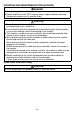
[STARTING AND MAINTENANCE PRECAUTIONS] DANGER ! Do not change the switch setting while power is on. ! Switch all phases of the GOT external power supply off before cleaning. Not doing so could result in electric shock. CAUTION ! Never disassemble or modify the module. This may cause breakdowns, malfunctioning, injury, and/or fire. ! Do not directly touch the conducted area and electric parts of this module. It may cause damage and malfunctioning of the module.
Revisions * The manual number is noted at the lower left of the back cover. Print Date *Manual Number Revision Jun., 1997 IB(NA)-68908-A First printing May, 2001 IB(NA)-68908-B Partial correction Chapter 1, Chapter 3, Chapter 4, Chapter 5, Chapter 7 Jun., 2004 IB(NA)-68908-C Partial correction SAFETY PRECAUTION, Manuals MODEL CODE change Changed from 13JL17 to 1DM053 This manual confers no industrial property rights or any rights of any other kind, nor does it confer any patent licenses.
CONTENTS 1. Overview........................................................................................................ 1 2. Components Including in the Package .......................................................... 1 3. Specifications ................................................................................................ 2 4. System configuration ..................................................................................... 7 5. User-fabricasted connection cables...................
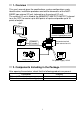
1. Overview This user's manual gives the specifications, system configurations, parts identifi-cation, installation procedure and outline dimensions of the A8GT50KBF type external I/O unit (referred to as the external I/O unit). The external I/O unit is fitted to the A956WGOT/A95*GOT/A85*GOT (referred to as the GOT) to receive up to 8/64 points of inputs and provide up to 16 points of outputs. GOT Operation panel, pushbutton, numeric keypad panel, etc.
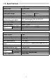
3. Specifications Input system Number of input points Isolation system Rated input voltage Rated input current Operating voltage range Max. number of simultaneous input points ON voltage/ON current OFF voltage/OFF current Input resistance ON to OFF Response time *1 OFF to ON Dynamic scan cycle Output system Number of output points Isolation system Rated load voltage Max. load current*4 Operating load voltage range Max. inrush current Leakage current at OFF Max.
I/O Specifications External connection system 40-pin connector Applicable wire size 0.3mm2 Operation indicator None 12/24VDC Voltage*3 (10.2 to 26.4V, ripple percentage 5% or less) External supply power 1.65A for external output Current 0.05A for internal consumption only Fuse rating*2 2.0A fuse, unreplaceable Internal current consumption 0.1A Weight 250g(0.55lb) 1 piece of external wiring connector Accessory (soldered type) *1: Time in the I/O section.
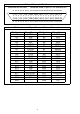
External Connector Pin-Outs View from the unit front Connector used: Fujitsu's FCN-365P040-AU B1 B2 B3 B4 B5 B6 B7 B8 B9 B10B11B12B13B14B15B16B17B18B19B20 A1 A2 A3 A4 A5 A6 A7 A8 A9 A10A11A12A13A14A15A16A17A18A19A20 Pin Numbers and Signal Names of External Connector Pin Number A1 A2 A3 A4 A5 A6 A7 A8 A9 A10 A11 A12 A13 A14 A15 A16 A17 A18 A19 A20 Signal Name XD7 XD5 XD3 XD1 XSCN7 XSCN5 XSCN3 XSCN1 YD15 YD13 YD11 YD9 YD7 YD5 YD3 YD1 DC12/24V DC12/24V 0V Pin Number B1 B2 B3 B4 B5 B6 B7 B8 B9 B10 B11 B12 B
External Connection Diagram (1) (8-point inputs, 16-point outputs) Pin number L L Internal control circuit R R B4 A4 B3 A3 B2 A2 B1 A1 XD0 XD1 XD2 XD3 XD4 XD5 XD6 XD7 B8 A8 B7 A7 B6 A6 B5 A5 XSCN0 XSCN1 XSCN2 XSCN3 XSCN4 XSCN5 XSCN6 XSCN7 R B16 A16 B15 A15 B14 A14 B13 A13 B12 A12 B11 A11 B10 A10 B9 A9 YD0 YD1 YD2 YD3 YD4 YD5 YD6 YD7 YD8 YD9 YD10 YD11 YD12 YD13 YD14 YD15 R Internal control circuit Internal scan is made at 1/8 duty.
External Connection Diagram (2) (64-point inputs, 16-point outputs) Pin number Input terminals 38 30 28 20 18 10 08 00 39 31 29 21 19 11 09 01 3A 32 2A 22 1A 12 0A 02 3B 33 2B 23 1B 13 0B 03 3C 34 2C 24 1C 14 0C 04 3D 35 2D 25 1D 15 0D 05 3E 36 2E 26 1E 16 0E 06 3F 37 2F 27 1F 17 0F 07 L L Internal control circuit R R B4 A4 B3 A3 B2 A2 B1 A1 XD0 XD1 XD2 XD3 XD4 XD5 XD6 XD7 B8 A8 B7 A7 B6 A6 B5 A5 XSCN0 XSCN1 XSCN2 XSCN3 XSCN4 XSCN5 XSCN6 XSCN7 R B16 A16 B15 A15 B14 A14 B13 A13 B12 A12 B11 A11 B10
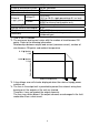
4. System Configuration (1) System configurations and connection conditions The following system configuration assumes connection of a printer. The numbers ( to ) given in the system configurations denote the numbers ( to ) in "(2) System equipment". Refer to these numbers when you want to confirm the types and applications. Connection Conditions System Configuration Numeric Keypad Panel Connection cable Max. 20m For input only Operation panel Connection cable Max.
(2) System equipment The following table indicates the system equipment needed for connection of external I/O equipment. Image No. Applocation Type External I/O GOT unit interface unit External I/O equipment-connected GOT A956WGOT, A95*GOT, A85*GOT Ten-key panel A8GT-TK Operation panel*1 FP5-MD41-A (Kanaden Corp. make), FP5-MD41-B (Kanaden Corp.
5. User-fabricated Connection Cables The following is the way of fabricating the connection cable which can be fabricated by the user: 5.1 Connection cable (1) Cable for connection between external I/O unit and original operator panel Fabricate the connection cable in accordance with the following wiring diagram, parts diagram and assembly drawing: (Maximum cable length: 20m (16.
(b) Parts list Number Name Type Maker Mitsubishi Electric 1) 2) Connector (with cover) A6CON1 1) 2) 3) 4) Connector Connector cover Pair shielded cable FG wire Wires for connection of external input power FCN-361JO40-AU FCN-360CO40-B UL 2464 AWG26 or equivalent UL 1015 AWG14 or equivalent 5) Fujitsu UL 1007 AWG24 or equivalent (c) Assembly 1) 2) DC power supply 12/24V 5) 3) User's desired connector 4) POINT " The cable fabricated should be within 3m in length .
(2) Cable for connection between external I/O unit and terminal block conversion unit. Fabricate the connection cable in accordance with the following wiring diagram, parts diagram and assembly drawing: (Maximum cable length: 10m (32.79feet)).
(b) Parts list Number Name 1) 2) 1) 2) 3) 4) Type Connector (with cover) A6CON1 Connector Connector cover Pair shielded cable FG wire FCN-361JO40-AU FCN-360CO40-B UL 2464 AWG26 or equivalent UL 1015 AWG14 or equivalent Maker Mitsubishi Electric Fujitsu (c) Assembly 1) 2) 4) 3) 1) 2) POINT " The cable fabricated should be within 3m in length . " Connect the FG cable to the nearest ground " The grounding wire (green wire, approx.
5.
(b) For use of the connection terminal block conversion unit (A6TBY54-E) Cable for connection between external I/O unit and connection terminal block A8GT-70KBF conversion unit 0 -C Shield 1 -C B4 XD0 A4 XD1 B3 XD2 A3 XD3 B2 XD4 A2 XD5 B1 XD6 A1 XD7 B8 XSCN0 A8 XSCN1 B7 XSCN2 A7 XSCN3 B6 XSCN4 A6 XSCN5 B5 XSCN6 A5 XSCN7 A9 YD0 B9 YD1 A10 YD2 B10 YD3 A11 YD4 B11 YD5 A12 YD6 B12 YD7 A13 YD8 B13 YD9 A14 YD10 B14 YD11 A15 YD12 B15 YD13 A16 YD14 B16 YD15 A17 DC12/24V B17 DC12/24V A18 DC12/24V 0V B18 0V A19 B19 E
00 08 10 18 20 15 Load Load Load Load Load Load Load Load Loads:Lamps,relays,etc.
00 08 10 18 20 16 A B 1D -C -C 1E -C -C 1C 9 1B 8 7 6 19 -C -C 1A -C -C XSCN0 XSCN1 XSCN2 XSCN3 XSCN4 XSCN5 XSCN6 XSCN7 18 5 07 0F 17 1F 27 XD7 17 A6TBY54-E 4 06 0E 16 1E 26 2F 37 XD6 3F Load Load 15 -C -C 16 3 05 0D 15 1D 25 2E 36 XD5 3E Load Load 14 2 0C 0C 14 1C 24 2D 35 34 2C XD4 3D XD3 3C Load Load 13 -C -C 03 0B 13 1B 23 2B 33 XD2 3B Load Load 11 -C -C 12 1 02 0A 12 1A 22 2A 32 XD1 3A Load Load 10 0 01 0
6. Pates Identification 2) 1) A8GT-50KBF 4) 2) 3) No. 2) Name I/O cable connection interface Unit fixing screws 3) Connector 4) Rating plate 1) Description Interface for connection of the I/O cable Screws used to fix the unit to the GOT Connector used to plug the unit to the GOT.
7. Installation Procedure Install the unit to the GOT in the following procedure: (1) Thread External I/O unit mounting screw holes in the control box or the like. (2-φ3.5 mounting holes) The External I/O unit’s GOT connection cable is 50cm long. Install the External I/O unit within this distance so that the GOT-end connector of the cable may be fitted into the GOT’s connector.
8. Outline Dimension Drawing 65 (2.56) 73 (2.87) A8GT-50KBF 92 (3.62) 9.5 (0.37) 105 (4.13) 44 (1.73) 500 (19.69) 42.6 (1.68) 67.8 (2.67) 3.2 (0.13) 3.5 (0.
20
21
Warranty Mitsubishi will not be held liable for damage caused by factors found not to be the cause of Mitsubishi; machine damage or lost profits caused by faults in the Mitsubishi products; damage, secondary damage, accident compensation caused by special factors unpredictable by Mitsubishi; damages to products other than Mitsubishi products; and to other duties.