
User`s manual


5
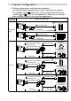
External Connection Diagram (1) (8-point inputs, 16-point outputs)
XD1
XD2
XD3
XD4
XD5
XD6
XD7
A8
B7
A7
B6
A6
B5
A5
XSCN0
XSCN1
XSCN2
XSCN3
XSCN4
XSCN5
XSCN6
XSCN7
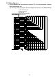
A16 YD1
B15 YD2
A15 YD3
B14 YD4
A14 YD5
B13 YD6
A13
YD7
B12 YD8
A12 YD9
B11 YD10
A11
YD11
B10 YD12
A10
YD13
B9 YD14
A9
YD15
R
R
B4
A4
B3
A3
B2
A2
B1
A1
XD0
B8
R
B16
R
YD0
L
L
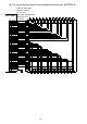
B18,A19
DC12/24V
(12/24VDC)
+-
A17,B17,A18
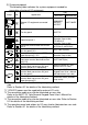
Pin number
Internal
control
circuit
Internal
control
circuit
Internal
control
circuit
Internal
scan is
made at
1/8 duty.
Fuse-blown
detector
circuit
*1: A fuse-blown error will also be displayed when the external supply power
switches off.
*2: The fuse in the output unit is provided to prevent the external wiring from
burning out if the outputs of the unit are shorted.
Therefore, it may not protect the output elements.
The fuse may not be blown if the output elements are damaged in the fault
mode other than a short circuit.