A8GT-TK type Numeric Keypad Panel User’s Manual (Hardware) Thank you for choosing the MELSEC-GOT Series. To ensure correct use of this equipment, please read this manual carefully before operating it.
z SAFETY PRECAUTIONS z (Always read before starting use) When using Mitsubishi equipment, thoroughly read this manual and the associated manuals introduced in the manual. Also pay careful attention to safety and handle the module properly. These precautions apply only to the installation of Mitsubishi equipment and the wiring with the external device. Refer to the user’s manual of the CPU module to be used for a description of the PLC system safety precautions.
[PRECAUTIONS REGARDING ASSEMBLY] DANGER z When connecting the connection cable to the Numeric Keypad Panel, always switch off GOT power externally in all phases. A failure to do so can cause misoperation due to miss-input. CAUTION z Use the Numeric Keypad Panel in the environment defined in the general specifications given in the GOT user's manual. Using it in other environment can cause an electric shock, fire, misoperation, or product damage or deterioration.
[PRECAUTIONS REGARDING AND MAINTENANCE] CAUTION z Do not disassemble or modify the Numeric Keypad Panel. This can cause a failure, misoperation, injury or fire. z The Numeric Keypad Panel case is made of resin.Do not drop it or give it hard impact. This can cause the product to be damaged or fail. z Always secure the connection cable connected to the Numeric Keypad Panel and the power wires drawn from the connection cable, e.g. run them in conduits or clamp them.
Revisions * The manual number is noted at the lower left of the back cover. Print Date *Manual Number Revision Nov., 1997 IB(NA)-68934-A First printing Apr., 2001 IB(NA)-68934-B Partial addition Chapter 1, Section 2.1, Section 2.2 Models added A9GT-70KBF Jun., 2004 IB(NA)-68934-C Partial correction About the Manuals MODEL CODE change Changed from 13JM76 to 1DM093 This manual confers no industrial property rights or any rights of any other kind, nor does it confer any patent licenses.
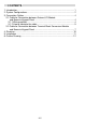
CONTENTS 1. Introduction.................................................................................................... 1 2. System Configurations................................................................................... 2 3. Connection Cables ........................................................................................ 4 3.1 Cable for Connection between External I/O Module and Numeric Keypad Panel ..................................................................... 4 3.1.
About the Manuals The following product are available for this equipment. Refer to the table given below to choose suitable manuals.
1. Introduction This user's manual gives specifications, handling instructions and other information of the A8GT-TK Numeric Keypad Panel (hereafter referred to as the "Numeric Keypad Panel"). First, please refer to the user's manual of the A9GT-70KBF/A8GT70KBF/A8GT-50KBF external I/O module (hereafter referred to as the "external I/O module") being used. The Numeric Keypad Panel is designed to be mountable onto a control box or the like.
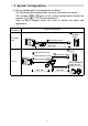
2. System Configurations (1) System configurations and connection conditions The following system configuration assumes connection of a printer. The numbers ( to ) given in the system configurations denote the numbers ( to ) in "(2) System equipment". Refer to these numbers when you want to confirm the types and applications. Connection conditions System configuration Numeric Keypad Panel For input only Connection cable Max.
(2) System equipment The following table indicates the system equipment needed for connection of external I/O equipment. Image No. Applicatin External GOT I/O GOT unit equipment-connected A985GOT, A97*GOT, A960GOT A870GOT, A810GOT A956WGOT, A95*GOT, A85*GOT Type External I/O interface module A9GT-70KBF A8GT-70KBF A8GT-50KBF Numeric keypad panel A8GT-TK Connector terminal block conversion unit*1 A6TBY36-E, A6TBY54-E Connection cable between [GOT] and [numeric keypad panel]*1*2 A8GT-C05TK(0.
3. Connection Cables This chapter provides how to wire and fabricate the connection cables. 3.1 Cable for Connection between External I/O Module and Numeric Keypad Panel Use the following cable for connection between the external I/O module and Numeric Keypad Panel. y Type A8GT-C05TK Numeric Keypad Panel connection cable (cable length:50cm (19.65 inch)) y User-fabricated connection cable (max. cable length:20m (65.62feet.)) 3.1.
3.1.2 How to fabricate the cable When you do not use the A8GT-C05TK Numeric Keypad Panel connection cable, fabricate the connection cable in accordance with the following wiring diagram and parts list (max. cable length: 20m (65.62 feet)).
(2) Parts list Number Name 1) Connector 2) 3) 4) Number 5) 6) 7) Connector cover Connector Connector cover Type Maker Qty FCN-361J040-AU 1 FCN-360C040-B FUJITSU LTD. 1 Tightening torque range: 35 to 48N·cm Japan Aviation D05-36PC-F0 Electronics 1 D05-36H-S Industry, Ltd. Name Type Twisted pair Conductor OD:1.0mm (0.04 inch) shielded cable (equivalent to UL 2935 AWG28) Conductor OD:1.8mm (0.07 inch) FG wire (equivalent to UL 1015 AWG14) External input power supply Conductor OD:0.6mm (0.
F1 F2 F3 F4 F5 F6 F7 F8 XD0 7 12/24VDC 1D -C -C 1E Load 1C Load 1B Load 19 -C -C 1A Load 18 Load 17 Load 15 -C -C 16 Load 14 Load 13 Load 11 -C -C 12 Load Load 10 Load Load Load Load Load Loads:Lamps,relays,etc. (A6TBY36-E) Terminal block conversion module 9 -C -C A 8 0 F9 XD1 F10 XD2 1 -C -C 2 XD3 3 SP XD4 4 XD5 XD6 5 -C -C 6 1 7 2 8 3 9 .
F1 F2 F3 F4 F5 F6 F7 F8 XD0 8 XD7 7 Load Load Load Load Load Load Load Loads:Lamps,relays,etc. 1D -C -C 1E 1C 1B B 19 -C -C 1A 9 -C -C A 8 18 (A6TBY54-E) Terminal block conversion module XD5 XD6 5 -C -C 6 XSCN 0 XSCN1 XSCN2 17 4 1 2 3 XSCN3 XSCN4 XSCN5 XSCN6 Load 15 -C -C 16 XD4 7 8 9 .
(2) Parts list Number Name Specifications Qty Solderless termi-nal 1.25-3.5 16 1) (with insulat-ion sleeve) Twisted pair Conductor OD: 1mm (0.04 inch) 2) 1 shielded cable (equivalent to UL 2935 AWG28) Number Name Type Maker Qty 3) Connector D05-36PC-F0 Japan Aviation Electronics 1 Connector Industry, Ltd.
4. Structure (Front) (Rear) 3) MELSEC/A8GT-TK F1 F2 F3 F4 F5 F6 F7 F8 F9 F10 SCROLL UP SCROLL DOWN 1) 2) 7 8 9 4 5 6 1 2 3 0 SP BS 3) Number 1) Keys 2) 3) Name Description Used to enter data. Connector for connection of the cable to Connector the external I/O module or terminal block conversion module. When the Numeric Keypad Panel is installed on a control box or the like, it is Installation screw holes fixed with M4 screws (user prepared).
5. Installation When installing the Numeric Keypad Panel on a control box door, mount or the like, the door or mount must be machined. The following diagram shows mounting panel machining dimensions. Mounting panel machining dimensions (front view) (13.75) {0.54} 172{0.77} Square hole 79{3.11} 32.75{1.29} 2f5 45{1.77} 25.5 {1.0} 25{0.98} (15.5) {0.
6. Outline Drawing 2-M4 screw,depth 5(0.20) MELSEC/A8GT-TK F2 F3 F4 F5 F6 F7 F8 F9 F10 SCROLL UP SCROLL DOWN 7 8 9 4 5 6 1 2 3 172(6.77) 197(7.76) F1 0 SP BS 70(2.76) 15 (0.59) 4.5(0.18) 45(1.
Warranty Mitsubishi will not be held liable for damage caused by factors found not to be the cause of Mitsubishi; machine damage or lost profits caused by faults in the Mitsubishi products; damage, secondary damage, accident compensation caused by special factors unpredictable by Mitsubishi; damages to products other than Mitsubishi products; and to other duties.