
Installation manual


- 16 -
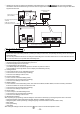
(3) Recommended circuit
1 Each element will turn on while in ON operation or if a malfunction occurs.
2 The connection cable can be extended up to 10m (32 ft).
3 The relays, lamps, diodes and extension cables, etc, must be prepared separately on site.
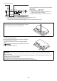
3. LAN connection function
When using the LAN connection function, insert the LAN cable to
the LAN connector of the controller.
* Procure the LAN cable on site, and use 100 BASE-T Straight
cable.
* For a description of the IP address setting method, refer to section
8 Initial Setting .
* LAN is 100 BASE-TX specification.
NOTE
• When connecting the external input/output cables to connector
CN5 on the controller, punch out the knockout hole.
CAUTION
* Perform the LAN wiring before controller installation, and wire up to the body by the same method as wiring the M-NET
transmission cable.
* When a LAN is already connected, choose the IP address after consulting with the system administrator, and connect to the
LAN body after changing the IP address.
* Connect AG-150A to a private network.
Use a security device such as a VPN router when connecting to the Internet.
(Configure the system in the way that does not allow access from the external sites.)
Use Z1 and Z2 relays that meet the following specifications.
Operation coil
Rated voltage: 12VDC, 24VDC
Power Consumption: 0.9W or less
(*1) Prepare a power supply separately according to the
relay being used (12VDC or 24VDC).
(*2) Always include a diode on both ends of the relay coil.
CN5
9
4
3
2
1
Brown
Black
Green
Max.10m
(32 ft)
L1Z1
L2
Z2
Z2
Z1
Power (*1)
Supply
Diode (*2)
(*2)
(*2)
This unit L1: Run display lamp
L2: Malfunction display lamp
Punch out the knockout hole
LAN