1A-0-1 ENGINE 6A1 SERIES CONTENTS GENERAL INFORMATION . . . . . . . . . . . . . . . . . . . . . . . . . . . . . . . . . . . . . . . . . . . 11A-0-3 1. SPECIFICATIONS . . . . . . . . . . . . . . . . . . . . . . . . . . . . . . . . . . . . . . . . . . . . . . . 11A-1-1 SERVICE SPECIFICATIONS . . . . . . . . . . . . . . . . . . . . . . . . . . . . . . . . . . 11A-1-1 REWORK DIMENSIONS . . . . . . . . . . . . . . . . . . . . . . . . . . . . . . . . . . . . . . . 11A-1-3 TORQUE SPECIFICATION . . . . . . . . .
11A-0-2 NOTES E Mitsubishi Motors Corporation Feb.
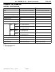
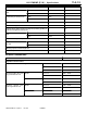
6A1 ENGINE (E - W) - General Information 11A-0-3 GENERAL INFORMATION GENERAL SPECIFICATIONS Descriptions 6A12 6A13 Type 60° V, OHV, DOHC (for each bank) 60° V, OHV, SOHC (for each bank) Number of cylinders 6 6 Combustion chamber Pentroof type Pentroof type Total displacement dm3 1,998 2,498 Cylinder bore mm 78.4 81.0 Piston stroke mm 69.0 80.8 Compression ratio 10.0 9.5*1 or 9.0*2 Opens (BTDC) 15° (Low-speed cam) 37.5° (High-speed cam) 15° Closes (ABDC) 41° (Low-speed cam) 82.
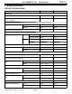
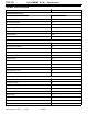
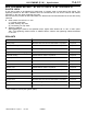
11A-1-1 6A1 ENGINE (E - W) - Specifications 1. SPECIFICATIONS SERVICE SPECIFICATIONS Items Standard value Limit Auto tensioner rod projection mm 12.0 - Auto tensioner rod pushed-in amount (when pushed with a force of 98 - 196 N) mm 1.0 or less - Intake 35.20 34.70 Exhaust 34.70 34.20 45 - (Low-speed cam) 34.34 33.84 (High-speed cam) 36.46 35.96 (Low-speed cam) 34.40 33.90 (High-speed cam) 35.86 35.36 26 - Intake 0.10 - Exhaust 0.
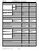
11A-1-2 6A1 ENGINE (E - W) - Specifications Items Standard value Limit SOHC 113.02 112.52 MIVEC 112.37 111.87 SOHC 115.32 114.82 MIVEC 110.74 110.74 SOHC 49.9 48.9 MIVEC 51.5 50.5 SOHC 265/43.4 - MIVEC 255/44.5 - Valve spring squareness 2° 4° Valve seat contact width mm 0.9 - 1.3 - Valve guide internal diameter mm 6.6 - Valve guide projection mm SOHC 14.0 - MIVEC 19.0 - Oil pump tip clearance mm 0.06 - 0.18 - Oil pump side clearance mm 0.04 - 0.
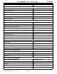
11A-1-3 6A1 ENGINE (E - W) - Specifications Items Standard value Limit Crankshaft journal diameter mm 6A12 53.0 - 6A13 56.0 - Crankshaft pin diameter mm 6A12 43.0 - 6A13 51.0 - Crankshaft journal oil clearance mm 0.02 - 0.04 0.1 Cylinder block gasket surface flatness mm 0.05 - Cylinder block gasket surface grinding limit (including grinding of cylinder head gasket surface) mm - 0.2 Cylinder block overall height mm 6A12 190.0 - 6A13 209.0 - 0.01 or less - 6A12 78.
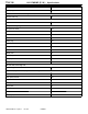
11A-1-4 6A1 ENGINE (E - W) - Specifications TORQUE SPECIFICATION Items Nm Alternator and drive belt Alternator pivot nut 44 Alternator bolt 21 Oil level gauge guide 23 Tensioner pulley 15 Engine hanger 23 Tensioner pulley bracket A 45 Crankshaft bolt 182 Engine cover 3 Timing belt Timing belt front cover 11 Engine support bracket 49 Angle sensor 9 Angle sensor connector bracket 11 Tensioner pulley 48 Tensioner arm 24 Auto tensioner 21 Camshaft sprocket bolt 88 Idler pulle
6A1 ENGINE (E - W) - Specifications Items Nm Ignition system Spark plug 25 Water cover (SOHC) 11 Distributor (SOHC) 13 Ignition failure sensor (MIVEC) 10 Condenser bracket assembly (MIVEC) 5 Ignition coil (MIVEC) 10 Water pump and water pipe Engine hanger (MIVEC) 11 Engine coolant temperature gauge unit 11 Engine coolant temperature sensor 29 Heater pipe (SOHC) 23 Water inlet fitting 18 Water outlet fitting 18 Thermostat housing 23 Water pipe 13 Water pump 23 Intake manifold
11A-1-6 6A1 ENGINE (E - W) - Specifications Items Nm Arm spring holder 11 Rocker arm and rocker shaft cap Rocker shaft cap 11 Cylinder head and valves Cylinder head bolt 20 + 120° + 120° Oil pan and oil pump Oil pressure switch 10 Oil filter cover 21 Water hose 30 Bolt 68 Drain plug 39 Oil level sensor 9 Oil pan 7 Oil screen 19 Baffle plate 9 Relief plug 44 Oil pump case 14 Oil pump case cover 12 Piston and connecting rod Connecting rod 18 + 90° - 100° Crankshaft,
6A1 ENGINE (E - W) - Specifications 11A-1-7 NEW TIGHTENING METHOD - BY USE OF BOLTS TO BE TIGHTENED IN PLASTIC AREA A new type of bolts, to be tightened in plastic area, is currently used in some parts of the engine. The tightening method for the bolts is different from the conventional one. Be sure to observe the method described in the text when tightening the bolts. Service limits are provided for the bolts. Make sure that the service limits described in the text are strictly observed.
A-1-8 6A1 ENGINE (E - W) - Specifications FORM-IN-PLACE GASKET (FIPG) The engine has several areas where the form-in-place gasket (FIPG) is in use. To ensure that the gasket fully serves its purpose, it is necessary to observe some precautions when applying the gasket. Bead size, continuity and location are of paramount importance. Too thin a bead could cause leaks. Too thick a bead, on the other hand, could be squeezed out of location, causing blocking or narrowing of the fluid feed line.
6A1 ENGINE (E - W) - Special Tools 11A-2-1 2. SPECIAL TOOLS Tool E Mitsubishi Motors Corporation Number Name Use MB990685 Torque wrench Adjustment of timing belt tension MB990938 Handle Use with MD998776 MB990767 Crankshaft pulley holder Holding camshaft sprocket when loosening and tightening of bolt.
11A-2-2 Tool E Mitsubishi Motors Corporation 6A1 ENGINE (E - W) - Special Tools Number Name Use MD998440 Leak-down tester Leak-down test of lash adjuster MD998441 Lash adjuster retainer Air bleeding of lash adjuster MD998442 Air bleed wire Air bleeding of lash adjuster MD998443 Lash adjuster holder Retainer for holding lash adjuster in rocker arm at time of removal and installation of rocker arm and rocker shaft assembly MD998713 Camshaft oil seal installer Installation of camshaft oil se
6A1 ENGINE (E - W) - Special Tools Tool E Mitsubishi Motors Corporation 11A-2-3 Number Name Use MD998735 Valve spring compressor Compression of valve spring MD998754 Pin Use with MB990767 MD998767 Tensioner pulley socket wrench Adjustment of timing belt tension MD998772 Valve spring compressor Removal and installation of valve and related parts MD998774 Valve stem seal installer Installation of valve stem seal MD998775 Valve stem seal installer Installation of valve stem seal MD99877
11A-2-4 Tool E Mitsubishi Motors Corporation 6A1 ENGINE (E - W) - Special Tools Number Name Use MD998780 SETTING TOOL Piston pin Removal and installation of piston pin MD998781 Flywheel stopper Holding flywheel and drive plate MD998784 Valve spring compressor adapter Compression of valve spring (MIVEC) (Use with MD998772) Feb.
6A1 ENGINE (E - W) - Drive Belt 11A-3-1 3. DRIVE BELT REMOVAL AND INSTALLATION 3 Nm 16 44 Nm 21 Nm 2 44 Nm 11 9 1 23 Nm 3 23 Nm 15 7 6 12 8 10 44 Nm 13 14 182 Nm 4 15 Nm 5 Removal steps 1. Drive belt 2. Alternator 3. Oil level gauge (dipstick) 4. Oil level gauge guide 5. O-ring 6. Tensioner pulley 7. Engine hanger 8. Tensioner pulley bracket A E Mitsubishi Motors Corporation Feb. 1997 9. 10. 11. AA" "AA 12. 13. 14. 15. 16.
11A-3-2 6A1 ENGINE (E - W) - Drive Belt REMOVAL AND INSTALLATION 3 Nm 16 21 Nm 44 Nm 2 1 11 44 Nm 9 3 13 23 Nm 23 Nm 7 6 10 14 44 Nm 8 4 15 Nm 15 12 182 Nm 5 Removal steps 1. Drive belt 2. Alternator 3. Oil level gauge (dipstick) 4. Oil level gauge guide 5. O-ring 6. Tensioner pulley 7. Engine hanger 8. Tensioner pulley bracket A E Mitsubishi Motors Corporation Feb. 1997 9. 10. 11. AA" "AA 12. 13. 14. 15. 16.
6A1 ENGINE (E - W) - Drive Belt 11A-3-3 REMOVAL SERVICE POINTS AA" CRANKSHAFT PULLEY BOLT REMOVAL (1) Hold the flywheel or drive plate in position with the special tool before removing the crankshaft pulley bolts. INSTALLATION SERVICE POINTS MD998781 E Mitsubishi Motors Corporation 6AE0039 Feb. 1997 "AA CRANKSHAFT PULLEY BOLT INSTALLATION (1) Hold the flywheel or drive plate in position with the special tool before installing the crankshaft pulley bolts.
11A-4-1 6A1 ENGINE (E - W) - Timing Belt 4. TIMING BELT REMOVAL AND INSTALLATION 11 Nm 6 88 Nm 35 Nm 17 16 15 14 48 Nm 24 Nm 8 12 13 18 11 9 11 Nm 7 5 1 11 Nm 21 Nm 3 10 2 4 9 Nm 49 Nm 11 Nm 11 Nm Removal steps 1. Timing belt front cover, upper right 2. Timing belt front cover, upper left 3. Timing belt front cover, lower 4. Engine support bracket 5. Angle sensor AA" "CA 6. Timing belt 7. Tensioner pulley 8. Tensioner arm 9.
11A-4-2 6A1 ENGINE (E - W) - Timing Belt REMOVAL AND INSTALLATION 12 Nm 23 21 11 Nm 88 Nm 11 Nm 17 16 22 48 Nm 9 10 18 19 11 5 35 Nm 8 6 17 44 Nm 11 Nm 15 14 12 20 1 13 22 Nm 2 11 Nm 7 9 Nm 9 Nm 49 Nm 9 Nm 4 3 11 Nm Removal steps 1. Timing belt front cover, upper right 2. Timing belt front cover, upper left 3. Timing belt front cover, lower 4. Engine support bracket 5. Angle sensor 6. Angle sensor 7. Spacer AA" "DA 8. Timing belt 9. Tensioner pulley 10. Tensioner arm 11.
6A1 ENGINE (E - W) - Timing Belt 11A-4-3 REMOVAL SERVICE POINTS AA" TIMING BELT REMOVAL (1) Mark the belt running direction for reference in reinstallation. (2) Loosen the bolt that secures the tensioner pulley to remove the timing belt. 6AE0135 6AE0044 AB" CAMSHAFT SPROCKET BOLT REMOVAL MB990767 MD998719 6AE0137 MB990767 MD998754 6AE0045 INSTALLATION SERVICE POINTS MD998719 "AA CAMSHAFT SPROCKET BOLT INSTALLATION MB990767 6AE0138 E Mitsubishi Motors Corporation Feb.
11A-4-4 6A1 ENGINE (E - W) - Timing Belt MD998754 MB990767 6AE0048 (B) "BA AUTO TENSIONER SETTING (1) Set the auto tensioner in a vice, while making sure it is not tilted. (2) Slowly close the vice to force the rod in until the set hole (A) of the rod is lined up with the set hole (B) of the cylinder. (A) 6AE0049 (3) Insert a 1.4 mm wire in the set hole. (4) Remove the auto tensioner from the vice.
6A1 ENGINE (E - W) - Timing Belt 6AE0331 11A-4-5 (3) Align the timing mark on the crankshaft sprocket with that on the cylinder block side. (4) Fit the timing belt on the sprockets in the following order: 1) Fit the timing belt on the crankshaft sprocket and then, while giving tension to the belt, fit it on the water pump sprocket. 2) Fit the belt on the left bank camshaft sprocket. 3) Fit the belt on the idler pulley while keeping it tight.
11A-4-6 6A1 ENGINE (E - W) - Timing Belt "DA TIMING BELT INSTALLATION (1) Turn the crankshaft sprocket so that its timing mark will be away from the mating timing mark by approx. three teeth. MD998716 Caution D If the timing marks are aligned, the piston is brought to the TDC. When the camshaft is turned under this condition, the valves may interfere with the piston. 6AE0051 (2) Bring the timing marks of the camshaft sprockets as shown in the illustration.
6A1 ENGINE (E - W) - Timing Belt 11A-4-7 4) On the left bank, make sure that the timing marks of the camshaft sprockets are aligned and then hold the timing belt on these sprockets with paper clips. 5) Place the timing belt around the water pump pulley. 6) Place the timing belt around the crankshaft sprocket. 7) Place the timing belt around the tensioner pulley. 6AE0056 (5) Move the tensioner pulley in the direction of the arrow and hold it in raised position by tightening the tensioner pulley bolt.
11A-4-8 6A1 ENGINE (E - W) - Timing Belt Cracks Peeling (2) (3) (4) (5) Cracks Cracks Cracks Cracks on rubber back. or peeling of canvas. on tooth bottom. or belt sides. Cracks Cracks 1EN0249 (6) Abnormal wear of belt sides. The sides are normal if they are sharp as if cut by a knife. Rounded edge Abnormal wear (Fluffy strand) 8EN0067 (7) Abnormal wear on teeth. (8) Missing tooth. Rubber exposed Tooth missing and canvas fiber exposed 8EN0068 AUTO-TENSIONER (1) Check for oil leaks.
11A-5-1 6A1 ENGINE (E - W) - Fuel and Emission Control Parts 5. FUEL AND EMISSION CONTROL PARTS REMOVAL AND INSTALLATION 12 Nm 6 18 Nm 22 Nm 7 18 Nm 18 Nm 2 3 5 4 8 18 Nm 9 18 Nm 1 9 Nm 12 Nm 20 10 11 19 16 15 21 17 23 Nm 22 14 13 18 9 Nm 12 Removal steps 1. Air intake plenum stay, front 2. Air intake plenum stay, rear 3. EGR valve 4. Gasket 5. Vacuum pipe 6. Throttle body "CA 7. Gasket 8. Air intake plenum 9. Gasket 10. Control harness 11.
11A-5-2 6A1 ENGINE (E - W) - Fuel and Emission Control Parts REMOVAL AND INSTALLATION 11 Nm 11 Nm 18 Nm 6 18 Nm 12 Nm 7 18 Nm 3 9 8.8 Nm 8 18 Nm 4 5 12 1 2 13 11 14 10 9 Nm 12 Nm 24 14 Nm 25 23 22 19 20 21 18 17 16 15 9 Nm 23 Nm 26 Removal steps 1. Air intake plenum stay, front 2. Air intake plenum stay, rear 3. Vacuum pipe 4. Throttle body "CA 5. Gasket 6. Connector bracket 7. Connector bracket 8. Accelerator cable bracket 9. Ignition failure sensor 10.
6A1 ENGINE (E - W) - Fuel and Emission Control Parts 11A-5-3 INSTALLATION SERVICE POINTS "AA FUEL PRESSURE REGULATOR INSTALLATION (1) Apply spindle oil or gasoline to the new O-ring installed on the fuel pressure regulator. (2) Insert the fuel pressure regulator in the delivery pipe. (3) Make sure that the fuel pressure regulator turns smoothly; then align the threaded holes and tighten the regulator bolts to specification.
11A-6-1 6A1 ENGINE (E - W) - Ignition System 6. IGNITION SYSTEM REMOVAL AND INSTALLATION 1 4 13 Nm 25 Nm 2 11 Nm 3 Removal steps 1. Spark plug cable 2. Spark plug 3. Water cover "AA 4. Distributor E Mitsubishi Motors Corporation Feb.
11A-6-2 6A1 ENGINE (E - W) - Ignition System REMOVAL AND INSTALLATION 1.0 Nm 25 Nm 1 3 2 Removal steps 1. Spark plug cable 2. Ignition coil 3. Spark plug INSTALLATION SERVICE POINT "AA DISTRIBUTOR INSTALLATION (1) Turn the crankshaft clockwise to bring the No. 1 cylinder piston to the compression stroke top dead center. (2) Align the mark on the distributor housing with the mark on the coupling. (3) Install the distributor while aligning the coupling key with the keyway in the camshaft end.
11A-7-1 6A1 ENGINE (E - W) - Water Pump and Water Pipe 7. WATER PUMP AND WATER PIPE REMOVAL AND INSTALLATION 18 Nm 4 9 23 Nm 18 Nm 29 Nm 3 5 2 10 6 8 13 Nm 1 14 11 Nm 12 11 23 Nm 13 23 Nm 15 Removal steps "FA 1. Engine coolant temperature gauge unit "EA 2. Engine coolant temperature sensor 3. Water hose 4. Water hose 5. Heater pipe 6. O-ring 7. Water inlet fitting E Mitsubishi Motors Corporation Feb. 1997 PWEE9622 "DA 8. Thermostat "CA 9. Water outlet fitting 10.
11A-7-2 6A1 ENGINE (E - W) - Water Pump and Water Pipe REMOVAL AND INSTALLATION 8 29 Nm 18 Nm 23 Nm 3 2 13 Nm 13 10 9 11 12 1 18 Nm 23 Nm 14 Removal steps 1. Engine hanger "FA 2. Engine coolant temperature gauge unit "EA 3. Engine coolant temperature sensor 4. Water hose 5. Water hose 6. Water inlet fitting "DA 7. Thermostat E Mitsubishi Motors Corporation Feb. 1997 PWEE9622 18 Nm 7 4 5 6 "CA 8. 9. 10. "BA 11. "BA 12. "BA 13. "AA 14.
11A-7-3 6A1 ENGINE (E - W) - Water Pump and Water Pipe 3 mm diameter bead sealant INSTALLATION SERVICE POINTS "AA SEALANT APPLICATION TO WATER PUMP Specified sealant: Mitsubishi Genuine equivalent Part No. MD970389 or 6AE0067 "BA WATER PIPE / O-RING INSTALLATION (1) Wet the O-ring (with water) to facilitate assembly. Caution D Keep the O-ring free of oil or grease. D Secure the water pipe after the thermostat housing has been installed.
11A-7-4 6A1 ENGINE (E - W) - Water Pump and Water Pipe "FA SEALANT APPLICATION TO ENGINE COOLANT TEMPERATURE GAUGE UNIT Specified sealant: 3M ATD Part No. 8660 or equivalent 6AE0071 E Mitsubishi Motors Corporation Feb.
11A-8-1 6A1 ENGINE (E - W) - Intake Manifold and Exhaust Manifold 8. INTAKE MANIFOLD AND EXHAUST MANIFOLD REMOVAL AND INSTALLATION 17 Nm 3 13 Nm 1 2 5 6 7 9 44 Nm 49 Nm 13 Nm 4 8 49 Nm Removal steps 1. Intake manifold 2. Gasket 3. Heat protector, right 4. Exhaust manifold stay 5. Exhaust manifold, right 6. Gasket 7. Heat protector, left 8. Exhaust manifold, left 9. Gasket E Mitsubishi Motors Corporation Feb.
11A-8-2 6A1 ENGINE (E - W) - Intake Manifold and Exhaust Manifold REMOVAL AND INSTALLATION 1 17 Nm 2 3 13 Nm 5 6 7 9 44 Nm 49 Nm 4 13 Nm 8 49 Nm Removal steps 1. Intake manifold 2. Gasket 3. Heat protector, right 4. Exhaust manifold stay 5. Exhaust manifold, right 6. Gasket 7. Heat protector, left 8. Exhaust manifold, left 9. Gasket E Mitsubishi Motors Corporation Feb.
11A-9-1 6A1 ENGINE (E - W) - Rocker Arm and Camshaft 9. ROCKER ARM AND CAMSHAFT REMOVAL AND INSTALLATION 4 Nm 31 Nm 1 2 6 3 10 9 5 8 9 8 9 7 13 7 7 8 12 24 Nm 12 11 12 14 16 15 17 Apply engine oil to all moving parts before installation. 4 "DA AA" "CA AA" "CA "CA Removal steps 1. Rocker cover 2. Rocker cover gasket 3. Oil seal 4. Oil seal 5. Rocker arm and rocker shaft 6. Rocker arm and rocker shaft 7. Rocker shaft spring 8. Rocker arm A 9.
11A-9-2 6A1 ENGINE (E - W) - Rocker Arm and Camshaft REMOVAL SERVICE POINT AA" ROCKER ARMS AND ROCKER ARM SHAFTS REMOVAL (1) Before removing rocker arms and shafts assembly, install the special tool as illustrated to prevent adjuster from dropping. MD998443 6AE0160 INSTALLATION SERVICE POINTS "AA CAMSHAFT INSTALLATION (1) Apply engine oil to journals and cams of the camshaft before installation. Be sure to install the correct camshafts on the correct bank.
11A-9-3 6A1 ENGINE (E - W) - Rocker Arm and Camshaft NOTE Install the rocker shaft spring before installing the exhaust side rocker arms and rocker arm shaft. (3) Remove the special tool for securing the lash adjuster. (4) Make sure that the notch in the rocker arm shaft is in the direction as illustrated. 6AE0163 "DA CAMSHAFT OIL SEAL INSTALLATION (1) When installing the left bank camshaft oil seal, use the special tool to prevent interference with the knock pin.
11A-9-4 6A1 ENGINE (E - W) - Rocker Arm and Camshaft LASH ADJUSTER LEAK DOWN TEST Caution D The lash adjuster is a precision part. Keep it free from dust and other foreign matters. D Do not disassemble lash adjuster. D When cleaning lash adjuster, use clean diesel fuel only. MD998442 Diesel fuel MD998441 6EN0186 (1) Immerse the lash adjuster in clean diesel fuel.
6A1 ENGINE (E - W) - Rocker Cover and Camshaft 11A-10-1 10. ROCKER COVER AND CAMSHAFT REMOVAL AND INSTALLATION 4 Nm 1 11 Nm 24 Nm 2 9 Nm 24 Nm 8 3 10 9 11 Nm 24 Nm 11 24 Nm 4 11 Nm Apply engine oil to all moving parts before installation. 9 12 13 6 14 5 7 Removal steps "GA 1. Rocker cover 2. Rocker cover gasket 3. Oil seal "FA 4. Circuit packing "EA 5. Oil seal "DA 6. Camshaft holder "DA 7. Semi-circular packing E Mitsubishi Motors Corporation Feb. 1997 "CA 8.
11A-10-2 6A1 ENGINE (E - W) - Rocker Cover and Camshaft INSTALLATION SERVICE POINT Left bank camshaft Right bank camshaft "AA CAMSHAFT INSTALLATION (1) Intake valve camshaft and exhaust valve camshaft can be identified by their diameters at the portions indicated in the illustration. Intake valve camshaft: 25 mm Exhaust valve camshaft: 30 mm 6AE0229 IN EX IN Dowel pin Right bank EX Dowel pin (2) Before installing each camshaft, apply engine oil to its journals and cams.
6A1 ENGINE (E - W) - Rocker Cover and Camshaft 11A-10-3 "CA OIL CONTROL VALVE INSTALLATION (1) Apply the specified sealant to the area shown. Specified sealant: 3M ATD Part No. 8660 or equivalent 6AE0236 "DA SEMI-CIRCULAR PACKING / CAMSHAFT HOLDER INSTALLATION (1) Make sure that the retainer of each adjusting screw is fitted correctly. Screw Protrusion Caution D If the protrusion on the retainer is not correctly fitted in the groove of the screw, the pad could slip off the retainer.
11A-10-4 6A1 ENGINE (E - W) - Rocker Cover and Camshaft "EA CAMSHAFT OIL SEAL INSTALLATION (1) When installing the left bank camshaft oil seal, use the special tool to prevent interference with the knock pin. Right bank MD998713 6AE0306 Left bank MD998777 MD998713 6AE0307 "FA CIRCULAR PACKING INSTALLATION MD998713 6AE0241 "GA ROCKER COVER INSTALLATION (1) Apply the specified sealant to the area shown. Specified sealant: 3M ATD Part No.
6A1 ENGINE (E - W) - Rocker Cover and Camshaft 11A-10-5 Valve 6AE0227 CAMSHAFT (1) Measure the cam heights. If the specified limit is exceeded, replace the camshaft. NOTE Each camshaft has an identification mark on its rear end surface. ( ): Identification mark IN (3) 9N0058 EX (C) High-speed cam (H) Identification mark location 16 mm 21 mm Standard value Limit L 34.34 mm 33.84 mm H 36.46 mm 35.96 mm L 34.40 mm 33.90 mm H 35.86 mm 35.
11A-10-6 6A1 ENGINE (E - W) - Rocker Cover and Camshaft (5) Screw in the other adjusting screw until it comes into contact with the valve (when the turning torque changes), and then tighten the lock nut. (6) Loosen the adjusting screw that was screwed in first slightly (until the turning torque becomes almost zero). Screw in the adjusting screw until it comes into contact with the valve again (when the turning torque changes) and tighten the lock nut. (7) Remove the thickness gauge.
6A1 ENGINE (E - W) - 11A-11-1 Rocker Arm and Rocker Shaft Cap 11. ROCKER ARM AND ROCKER SHAFT CAP REMOVAL AND INSTALLATION 22 20 21 13 20 13 21 13 14 19 20 21 11 12 15 4 18 16 11 12 17 3 4 5 10 11 12 7 1 2 6 11 Nm 9 8 Apply engine oil to all moving parts before installation. 4 Removal steps "BA 1. Rocker shaft cap 2. Seal cap A 3. Seal cap C 4. Intake rocker arm assembly A 5. Nut 6. Adjusting screw 7. Intake rocker arm H 8. Piston H 9. Piston spring H 10.
11A-11-2 6A1 ENGINE (E - W) T-lever Spring guide Waved washer Rocker Arm and Rocker Shaft Cap INSTALLATION SERVICE POINTS "AA SPRING GUIDE INSTALLATION (1) Install the spring guide with the concave side toward the rocker arm. The waved washer may be installed with either side out. Concave side Either side may be out 6 5 2 1 4 3 6AE0247 "BA ROCKER SHAFT CAP INSTALLATION (1) Tighten the bolts in the sequence shown. (2) Make sure that each rocker arm moves smoothly.
6A1 ENGINE (E - W) - Cylinder Head and Valves 11A-12-1 12. CYLINDER HEAD AND VALVES REMOVAL AND INSTALLATION 1 4 5 6 12 20 13 16 17 19 14 8 9 15 10 11 18 7 3 Apply engine oil to all moving parts before installation. Removal steps AA" "DA 1. Cylinder head bolt 2. Cylinder head 3. Cylinder head gasket AB" "CA 4. Retainer lock 5. Valve spring retainer "BA 6. Valve spring 7. Intake valve AB" "CA 8. Retainer lock 9. Valve spring retainer "BA 10.
11A-12-2 6A1 ENGINE (E - W) - Cylinder Head and Valves REMOVAL AND INSTALLATION 1 4 5 12 8 9 6 13 14 10 15 16 17 2 20 19 18 11 7 3 Apply engine oil to all moving parts before installation. Removal steps AA" "DA 1. Cylinder head bolt 2. Cylinder head 3. Cylinder head gasket AB" "CA 4. Retainer lock 5. Valve spring retainer "BA 6. Valve spring 7. Intake valve AB" "CA 8. Retainer lock 9. Valve spring retainer "BA 10. Valve spring E Mitsubishi Motors Corporation Feb. 1997 AD" 11.
6A1 ENGINE (E - W) - Cylinder Head and Valves 11A-12-3 REMOVAL SERVICE POINTS PRECAUTION FOR REMOVED PARTS Keep removed parts in order according to the cylinder number and intake/exhaust side. MB991653 AA" CYLINDER HEAD BOLT REMOVAL (1) Using the special tool, loosen the cylinder head bolts. Loosen evenly, little by little. 6AE0166 MB991653 6AE0408 AB" RETAINER LOCK REMOVAL (1) Store removed valves, springs and other parts, tagged to indicate their cylinder Nos.
11A-12-4 6A1 ENGINE (E - W) - Cylinder Head and Valves AC" VALVE STEM SEAL REMOVAL (1) Do not reuse removed valve stem seals. 6AE0082 AD" VALVE HANDLING PRECAUTIONS (1) Sodium reacts violently with water or moisture generation heat and liberating hydrogen. It must be handled with utmost care because otherwise the following dangerous conditions may result: Loss of eyesight if sodium gets in eyes. Burns if sodium contact skin. Fire hazard.
6A1 ENGINE (E - W) - Cylinder Head and Valves 11A-12-5 INSTALLATION SERVICE POINTS Stem seals for intake valves: Silver Stem seals for exhaust valves: Black 7EN0763 "AA VALVE STEM SEAL INSTALLATION (1) Install the valve spring seat. (2) Use the special tool to fit a new stem seal on the valve guide. NOTE Valve stem seals for intake valves are different from those for exhaust valves.
11A-12-6 6A1 ENGINE (E - W) - Cylinder Head and Valves MD998784 MD998772 6AE0253 MD998735 6EN1068 "DA CYLINDER HEAD BOLT INSTALLATION (1) When installing the cylinder head bolts, check that the shank length of each bolt meets the limit. If the limit is exceeded, replace the bolts. Limit: max. 96.4 mm (2) Install the washers as illustrated. (3) Apply engine oil to the bolt threads and washers.
11A-12-7 6A1 ENGINE (E - W) - Cylinder Head and Valves INSPECTION CYLINDER HEAD (1) Check the cylinder head gasket surface for flatness by using a straightedge and thickness gauge. Standard value: 0.03 mm Limit: 0.2 mm (2) If the service limit is exceeded, correct to meet the specification. 6AE0083 Grinding limit: *0.2 mm *Includes/combined with cylinder block grinding Cylinder head height (Specification when new): 119.9 - 120.1 mm 119.6 - 119.
11A-12-8 6A1 ENGINE (E - W) - Cylinder Head and Valves Out of square VALVE SPRING (1) Measure the valve spring’s free height. If the measurement is less than specified, replace the spring. Standard mm Free height 1EN0264 value Limit mm SOHC 49.9 48.9 MIVEC 51.5 50.5 (2) Measure the squareness of the spring. If the measurement exceeds the specified limit, replace the spring.
6A1 ENGINE (E - W) - Cylinder Head and Valves 0.9 - 1.3 mm 0.9 - 1.3 mm 65_ 65_ 15_ 44_ 44_ 15_ 1EN0105 11A-12-9 VALVE SEAT RECONDITIONING PROCEDURE (1) Before correcting the valve seat, check the clearance between the valve guide and valve. If necessary, replace the valve and/or valve guide. (2) Using the appropriate special tool or seat grinder, correct the valve seat to achieve the specified seat width and angle.
11A-12-10 6A1 ENGINE (E - W) - Cylinder Head and Valves (3) Press-fit the valve guide until it protrude specified value (SOHC: 14 mm, DOHC: 19 mm) as shown in the illustration. Caution D Press the valve guide from the cylinder head top surface. D Valve guide for intake valve and that for exhaust valve are different in length. (45.5 mm for intake valve; 50.5 mm for exhaust valve) 14 mm 1EN0106 (4) After the valve guide has been installed, insert a new valve to check for smooth sliding motion.
11A-13-1 6A1 ENGINE (E - W) - Oil Pump Case and Oil Pan 13. OIL PUMP CASE AND OIL PAN REMOVAL AND INSTALLATION 6 Apply engine oil to all moving parts before installation. 12 Nm 26 24 25 2 22 14 Nm 8 23 1 7 19 Nm 20 19 21 17 16 4 21 Nm 5 68 Nm 15 30 Nm 9 Nm 18 10 Nm 44 Nm 3 7 Nm 14 12 10 39 Nm 7 Nm 9 13 9 Nm 11 Removal steps "IA 1. Oil pressure switch "HA 2. Oil filter 3. Oil filter cover 4. Water hose (for Europe and GCC) 5. Water pipe (for Europe and GCC) 6.
11A-13-2 6A1 ENGINE (E - W) - Oil Pump Case and Oil Pan REMOVAL AND INSTALLATION 2 17 18 21 Nm 14 14 Nm 9 12 Nm 3 16 15 13 12 11 44 Nm 10 1 7 Nm 8 7 19 Nm 10 Nm 7 Nm 6 39 Nm 4 5 Apply engine oil to all moving parts before installation. Removal steps "IA 1. Oil pressure switch "HA 2. Oil filter 3. Oil filter cover 4. Drain plug "FA 5. Gasket AA" "EA 6. Oil pan 7. Oil screen 8. Gasket 9. Buffle plate E Mitsubishi Motors Corporation Feb. 1997 "CA "BA "AA "AA PWEE9622 10. 11.
11A-13-3 6A1 ENGINE (E - W) - Oil Pump Case and Oil Pan REMOVAL SERVICE POINT MD998727 AA" OIL PAN REMOVAL (1) Knock the special tool deeply between the oil pan and the cylinder block. (2) Hitting the side of the special tool, slide the special tool along the oil pan to remove it. 6AE0087 INSTALLATION SERVICE POINTS "AA INNER ROTOR / OUTER ROTOR INSTALLATION (1) Apply engine oil to the rotors. Then, install the rotors ensuring that the alignment dots made at disassembly are properly aligned.
11A-13-4 6A1 ENGINE (E - W) - Oil Pump Case and Oil Pan "DA OIL PAN INSTALLATION (1) Clean the cylinder block and oil pan gasket application surfaces. (2) Install the oil pan within 15 minutes after FIPG has been applied to the entire flange surfaces of the oil pan. Specified sealant: Mitsubishi Genuine equivalent Part No. MD970389 or f4 Groove Bolt hole "EA OIL PAN INSTALLATION (1) Clean the cylinder block and oil pan gasket application surfaces.
6A1 ENGINE (E - W) - Oil Pump Case and Oil Pan 11A-13-5 "GA OIL COOLER INSTALLATION (1) Install the oil cooler, with the oil cooler’s positioning projection positioned against the rib on cylinder block. 6AE0172 "HA OIL FILTER INSTALLATION (1) Clean the surfaces of the cylinder block on which the oil filter is to be mounted. (2) Apply engine oil to the O-ring of the oil filter.
11A-13-6 6A1 ENGINE (E - W) - Oil Pump Case and Oil Pan (3) Check the body clearance. Standard value: 0.10 - 0.18 mm Limit: 0.35 mm 6AE0090 OIL LEVEL SENSOR (FOR EUROPE) (1) Put the oil level sensor in the oil, then move the float up and down with the oil at a temperature either lower than 40°C or higher than 80°C, and check for continuity.
6A1 ENGINE (E - W) - Piston and Connecting Rod 11A-14-1 14. PISTON AND CONNECTING ROD REMOVAL AND INSTALLATION Apply engine oil to all moving parts before installation. 6AE0095 "GA AA" "FA "EA "DA "EA "CA Removal steps 1. Nut 2. Connecting rod cap 3. Connecting rod bearing 4. Piston and connecting rod 5. Connecting rod bearing 6. Piston ring No.1 E Mitsubishi Motors Corporation Feb. 1997 "CA 7. Piston ring No.2 "BA 8. Oil ring AB" "AA 9. Piston pin 10. Piston 11. Connecting rod 12.
11A-14-2 6A1 ENGINE (E - W) - Piston and Connecting Rod REMOVAL SERVICE POINTS Cylinder No. AA" CONNECTING ROD CAP REMOVAL (1) Mark the large end of the connecting rod with the cylinder number for use during reassembly. DEN0050 Piston pin setting tool MD998780 Push rod Guide A: 17.9 mm AB" PISTON PIN REMOVAL Piston pin setting tool (MD998780) consists of the parts shown in the illustration at left.
6A1 ENGINE (E - W) - Piston and Connecting Rod INSTALLATION SERVICE POINTS Piston B A C D Connecting rod Piston pin 11A-14-3 "AA PISTON PIN INSTALLATION (1) Measure the following dimensions of the piston, piston pin and connecting rod. A: Piston pin insertion hole length B: Distance between piston bosses C: Piston pin length D: Connecting rod small end width (2) Calculate the following formula by substituting the measured values.
11A-14-4 6A1 ENGINE (E - W) - Piston and Connecting Rod "BA OIL RING INSTALLATION (1) Fit the oil ring spacer into the piston ring groove. NOTE The side rails and spacer may be installed in either direction. (2) Install the upper side rail. To install the side rail, first fit one end of the rail into the piston groove, then press the remaining portion into position by finger. See illustration. 6AE0194 NOTE Do not use piston ring expander when installing side rail.
6A1 ENGINE (E - W) - Piston and Connecting Rod 11A-14-5 (4) Use suitable thread protectors on connecting rod bolts before inserting piston and connecting rod assembly into cylinder block. Care must be taken not to nick crank pin. (5) Using a suitable piston ring compressor tool, install piston and connecting rod assembly into the cylinder block. Caution D Insert the front mark (arrow) on the top of the piston so it faces the engine front (timing belt side). 6AE0097 Crankshaft pin identification mark No.
11A-14-6 6A1 ENGINE (E - W) - Piston and Connecting Rod (2) Check if the thrust clearance in the connecting rod big end is correct. Standard value: 0.10 - 0.25 mm Limit: 0.4 mm 9EN0073 "GA CONNECTING ROD CAP NUT INSTALLATION (1) Since the connecting rod bolts and nuts are torqued using a new procedure they should be examined BEFORE reuse. If the bolt threads are “necked down” the bolts should be replaced. Necking can be checked by running a nut with fingers to the full length of the bolt’s thread.
6A1 ENGINE (E - W) - Piston and Connecting Rod 11A-14-7 INSPECTION PISTON RING (1) Check the side clearance between the piston ring and ring groove. If the limit is exceeded, replace the ring or piston, or both. Standard value: No. 1 0.03 - 0.07 mm No. 2 0.02 - 0.06 mm 7EN0475 Push in by the piston 0.1 mm 0.1 mm Install the piston ring into the cylinder bore. Force it down with a piston, its crown being in contact with the ring, to correctly position it at right angles to the cylinder wall.
6A1 ENGINE (E - W) - Crankshaft, Cylinder Block, Flywheel and Drive Plate 11A-15-1 15. CRANKSHAFT, CYLINDER BLOCK, FLYWHEEL AND DRIVE PLATE REMOVAL AND INSTALLATION 5 4 6 11 Nm 35 Nm 2 23 Nm A 11 3 1 14 98 Nm 13 7 21 8 12 98 Nm 9 11 Nm 10 9 Nm 19 18 20 Apply engine oil to all moving parts before installation. 17 16 15 "EA "EA "DA "CA "BA Removal steps 1. Detonation sensor 2. Idler pulley bracket 3. Flywheel bolt 4. Plate 5. Adapter plate 6.
11A-15-2 6A1 ENGINE (E - W) - INSTALLATION SERVICE POINTS Crankshaft journal identification mark No.1 Crankshaft, Cylinder Block, Flywheel and Drive Plate "AA CRANKSHAFT BEARING INSTALLATION (1) When replacing bearing, select a one of proper size according to the identification marks stamped on both crankshaft and cylinder block. No.2 No.4 <6A12> No.3 Check digit 6AE0343 No.4 No.3 Cylinder bore size mark (reference) No.
6A1 ENGINE (E - W) - Crankshaft, Cylinder Block, Flywheel and Drive Plate 11A-15-3 "BA BEARING CAP / BEARING CAP BOLT INSTALLATION (1) Install the bearing caps so that their arrows are positioned on the timing belt side. (2) When installing the bearing cap bolts, check that the shank length of each bolt meets the limit. If the limit is exceeded, replace the bolt. Shank length Limit: max. 71.1 mm 9EN0477 (3) Apply engine oil to the threaded portion and bearing surface of the bolt.
11A-15-4 6A1 ENGINE (E - W) - Crankshaft, Cylinder Block, Flywheel and Drive Plate "CA OIL SEAL INSTALLATION (1) Apply engine oil to oil seal lip. MB990938 MD998776 9EN0077 "DA APPLICATION OF OIL SEAL CASE Specified sealant: Mitsubishi Genuine equivalent Part No. MD970389 or 6AE0110 "EA DRIVE PLATE BOLT / FLYWHEEL BOLT INSTALLATION (1) Remove all the remaining sealant from bolts and thread holes of crankshaft. (2) Apply engine oil to the flange of bolt.
6A1 ENGINE (E - W) A C D B E Crankshaft, Cylinder Block, Flywheel and Drive Plate 11A-15-5 CYLINDER BLOCK (1) Using a straightedge and feeler gauge, check the block top surface for warpage. Make sure that the surface is free from gasket chips and other foreign matter. F G Standard value: 0.05 mm or less Limit: 0.1 mm (2) If the distortion is excessive, correct within the allowable limit or replace. 6AE0103 Grinding limit: 0.
11A-15-6 6A1 ENGINE (E - W) - Crankshaft, Cylinder Block, Flywheel and Drive Plate (4) Bore all cylinders to calculated boring finish dimension. Caution D To prevent distortion that may result from temperature rise during honing, bore cylinders, working from No. 1, No. 2, No. 3, No. 4, No. 5 and No. 6 (5) Hone to final finish dimension (piston O.D. + clearance between piston O.D. and cylinder.) (6) Check clearance between piston and cylinder. Clearance between piston and cylinder: 0.02 - 0.
NOTES
Service Bulletins Click on the applicable bookmark to select the Service Bulletin.
SERVICE BULLETIN QUALITY INFORMATION ANALYSIS OVERSEAS SERVICE DEPT. MITSUBISHI MOTORS CORPORATION SERVICE BULLETIN Subject: Group: No.: MSB-01E11-001 Date: 2001-07-25 ADDITION OF 6A1 ENGINE WATER PUMP INSTALLATION PROCEDURES ENGINE Draft No.: 00EN620614 INFORMATION INTERNATIONAL CAR ADMINISTRATION OFFICE (EC)GALANT(EA0) 01-10 T.MASAKI-MANAGER TECHNICAL SERVICE PLANNING 1.
ENGINE 6A1 (E-W) Workshop Manual 6A1 ENGINE (E-W) – Water Pump and Water Pipe 11A-7-3 INSTALLATION SERVICE POINTS 3 mm diameter bead sealant ►A◄ SEALANT APPLICATION TO WATER PUMP Specified sealant: Mitsubishi Genuine Part No. MD970389 or equivalent 4th page added here. 6AE0067 ►B◄ WATER PIPE / O-RING INSTALLATION (1) Wet the O-ring (with water) to facilitate assembly. Caution • Keep the O-ring free of oil or grease. • Secure the water pipe after the thermostat housing has been installed.
(1) Install the water pump and tighten the bolts 1 and 2 in that order. (2) Turn the pulley by hand and ensure that the impeller does not interfere with the cylinder block. (3) Tighten the bolts other than bolts 1 and 2.