
Service manual


22
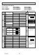
8-2. FUNCTION OF DIP SWITCH
1
2
3
4
5
6
7
8
9
10
1~4
1
2
3
4
5
6
7
8
9
10
Thermistor<Intake temperature>
position
ON OFF
Filter clogging Provide Not provide
Filter sign indication 2,500 hr 100 hr
Air intake Not effective Not effective
Remote indication switching Thermo ON signal indication Fan output indication
Humidifier control
Fan operation at Heating mode
Thermo ON operation at
heating mode
Extra low *1
Setting air flow *1 Depends on SW1-7
Auto restart function Effective Not effective
Power ON/OFF Effective Not effective
Heat pump/Cool only Cooling only Heat pump
Louver
Vane
Vane swing
Available Not available
Vane horizontal angle Second setting First setting
Vane cooling limit angle setting
Horizontal angle Down B,C
Effective Not effective
Heating 4 degree up Not effective Effective
Superheat setting temperature
*2 —
—
—
—
—
—
Subcool setting temperature
*2 — —
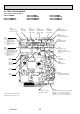
ON
OFF
12345678910
ON
OFF
12345678910
ON
OFF
1234
ON
OFF
1234
P20
Models SW2
P25
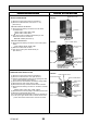
Address board
Indoor controller board
Indoor controller board
<Initial setting>
SW3
Function
selection
Under
suspension
SW2
Capacity
code
Before
power
supply
ON
switch
SW1
Mode
Effective
timing
Under
suspension
selection
Switch
Pole
Function
Operation by switch
Remarks
Built-in remote controller
Indoor unit
Changing the opening of linear
expansion valve
*1
SW1-7
OFF
ON
OFF
ON
SW1-8
OFF
OFF
ON
ON
Fan speed
Extra low
Low
Setting air flow
Stop
*2 It is impossible to intake
the fresh air.
Set for each capacity.
*1
*2
*3
At cooling mode, each angle
can be used only 1 hour.
Please do not change SW3-9,
3-10 as trouble might be
caused by the usage condition.
Air flow set in case of heat
thermo OFF
NOTE:
*2
*1
ON
OFF
1234
P15
<Initial setting>
<Initial setting>
Low *1
*3
Second setting is the same
as first setting.
PKFY-P15VBM-E PKFY-P20VBM-E PKFY-P25VBM-E
PKFY-P20VBM-ER1 PKFY-P25VBM-ER1
PKFY-P15VBM-ER2 PKFY-P20VBM-ER2 PKFY-P25VBM-ER2
PKFY-P15VBM-ER3 PKFY-P20VBM-ER3 PKFY-P25VBM-ER3
The black square ( ) indicates a switch position.
OCH418C