
Service manual


1234 56789
10
1
2
3
4
5
6
7
8
9
0
1
2
3
4
5
6
7
8
9
0
1
2
3
4
5
6
7
8
9
A
B
C
D
E
F
0
27
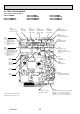
8-3-2. Indoor power board
PKFY-P15VBM-E PKFY-P20VBM-E PKFY-P25VBM-E
PKFY-P20VBM-ER1 PKFY-P25VBM-ER1
PKFY-P15VBM-ER2 PKFY-P20VBM-ER2 PKFY-P25VBM-ER2
PKFY-P15VBM-ER3 PKFY-P20VBM-ER3 PKFY-P25VBM-ER3
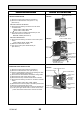
8-3-3. Address board
PKFY-P15VBM-E PKFY-P20VBM-E PKFY-P25VBM-E
PKFY-P20VBM-ER1 PKFY-P25VBM-ER1
PKFY-P15VBM-ER2 PKFY-P20VBM-ER2 PKFY-P25VBM-ER2
PKFY-P15VBM-ER3 PKFY-P20VBM-ER3 PKFY-P25VBM-ER3
SW1
Function setting
SW12
Address setting
10ths digit
SW11
Address setting
1s digit
FUSE
6.3A 250V
CN53P
Connected to the indoor controller board
(CN53M)
Between 1 to 2 24-30V DC (non-polar)
Between 3 to 5 12.5-13.7V DC (Pin3 (+))
Between 4 to 5 11.5-12.7V DC (Pin4 (+))
CN35P
Connected to the indoor controller board
(CN35M)
CN2M
Connected to the terminal block (TB5)
(M-NET transmission connecting wire)
24-30V DC (non-polar)
FAN
Fan motor output (MF)
CND
Power supply for
indoor controller board
Between 1 to 3 220-240V AC
LED1
Indication of main power
supply ON/OFF
OCH418C