
Service manual


32
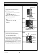
3. REMOVING THE INDOOR CONTROLLER BOARD AND
INDOOR POWER BOARD
(1) Remove the front panel. (Refer to procedure 2)
(2) Remove the electrical box cover (screw 4 × 10).
(See Photo 2)
INDOOR CONTROLLER BOARD
(1) Disconnect the following connectors from the indoor con-
troller board.
CN60, CN5V, CN90, CN29, CN21
CN42, CN81, CN3A, CN20
(2) Pull out the indoor controller board toward you, then dis-
connect the rest of connectors.
CN53M, CN35M (See Photo 3)
INDOOR POWER BOARD
(1) Disconnect the following connectors on the indoor power
board.
FAN, CN53P, CN35P, CN2M, CND
(2) Remove the earth wire for TAB1.
(3) Pull out the indoor power board toward you.
(See Photo 3)
Photo 2
Electrical box
cover
Electrical box
Photo 3
Indoor controller board
Indoor power
board
Room temperature
thermistor (TH21)
Screw for
electrical box
cover
Electrical box
Water cut
fixing screw
Water cut
4. REMOVING THE NOZZLE ASSEMBLY AND DRAIN HOSE
(1) Remove the front panel. (Refer to procedure 2)
(2) Remove the electrical box cover. (See Photo 2)
(3) Disconnect the connector (CN5V) on the indoor controller
board.
(4) After unhook the right side of the corner box, press the
upper left side and remove the corner box.
(5) Remove the nozzle assembly from the fixture.
(See Photo 4)
(6) Remove the drain hose.
Photo 4
Heat exchanger
Electrical box
Fixture for
nozzle assembly
Drain hose
Nozzle assembly
5. REMOVING THE FAN GUARD
(1) Remove the nozzle assembly and drain hose. (Refer to
procedure 4)
(2) Remove the screws of fan guard. (See Photo 5)
(3) Remove the fan guard.
Screws for
fan guard
Photo 5
PHOTOS & ILLUSTRATIONSOPERATION PROCEDURE
OCH418C