SPLIT-TYPE, HEAT PUMP AIR CONDITIONERS December 2012 TECHNICAL & SERVICE MANUAL Indoor unit [Model names] PLFY-P32VBM-E PLFY-P40VBM-E PLFY-P50VBM-E PLFY-P63VBM-E PLFY-P80VBM-E PLFY-P100VBM-E PLFY-P125VBM-E [Service Ref.] PLFY-P32VBM-E.UK PLFY-P32VBM-ER2.UK PLFY-P40VBM-E.UK PLFY-P40VBM-ER2.UK PLFY-P50VBM-E.UK PLFY-P50VBM-ER2.UK PLFY-P63VBM-E.UK PLFY-P63VBM-ER2.UK PLFY-P80VBM-E.UK PLFY-P80VBM-ER2.UK PLFY-P100VBM-E.UK PLFY-P100VBM-ER3.UK PLFY-P125VBM-E.UK PLFY-P125VBM-ER3.UK PLFY-P32VBM-E1.
1 TECHNICAL CHANGES PLFY-P32VBM-ER2.UK PLFY-P40VBM-ER2.UK PLFY-P50VBM-ER2.UK PLFY-P63VBM-ER2.UK PLFY-P80VBM-ER2.UK PLFY-P100VBM-ER2.UK PLFY-P125VBM-ER2.UK PLFY-P32VBM-ER3.UK PLFY-P40VBM-ER3.UK PLFY-P50VBM-ER3.UK PLFY-P63VBM-ER3.UK PLFY-P80VBM-ER3.UK PLFY-P100VBM-ER3.UK PLFY-P125VBM-ER3.UK INDOOR CONTROLLER BOARD (I.B) has been changed. (S/W version up) PLP-6BAJ (Automatic filter elevation panel, option) The controller board (U.B) has been changed.
2 SAFETY PRECAUTION Cautions for units utilizing refrigerant R410A Use the following tools specifically designed for use with R410A refrigerant. Do not use the existing refrigerant piping. The old refrigerant and lubricant in the existing piping contains a large amount of chlorine which may cause the lubricant deterioration of the new unit. The following tools are necessary to use R410A refrigerant.
[1] Cautions for service (1) Perform service after recovering the refrigerant left in unit completely. (2) Do not release refrigerant in the air. (3) After completing service, charge the cycle with specified amount of refrigerant. (4) When performing service, install a filter drier simultaneously. Be sure to use a filter drier for new refrigerant. [2] Additional refrigerant charge When charging directly from cylinder · Check that cylinder for R410A on the market is syphon type.
3 PART NAMES AND FUNCTIONS 3-1.
3-2. WIRELESS REMOTE CONTROLLER CHECK TEST RUN display CHECK and TEST RUN display indicate that the unit is being checked or test-run. MODEL SELECT display Blinks when model is selected. display Lights up while the signal is transmitted to the indoor unit when the button is pressed. display SET TEMP. display indicates the desired temperature which is set. CLOCK display display Displays the current time. OPERATION MODE display Operation mode display indicates which operation mode is in effect.
3-3. WIRED REMOTE CONTROLLER Wired remote controller function * The functions which can be used are restricted according to the model.
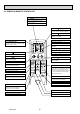
The main display can be displayed in two different modes: "Full" and "Basic". The factory setting is "Full". To switch to the "Basic" mode, change the setting on the Main display setting. * All icons are displayed for explanation. Fri Fri Cool Room Cool Set temp. Mode Temp. Set temp. Auto Auto Mode Fan Temp. Fan Operation mode Indoor unit operation mode appears here. Appears when the buttons are locked. Preset temperature Preset temperature appears here.
Menu structure Main menu Press the MENU button. Move the cursor to the desired item with the F1 and F2 buttons, and press the SELECT button. Vane · Louver · Vent. (Lossnay) High power Timer On / Off timer Auto-Off timer Filter information Error information Weekly timer Energy saving Auto return Schedule Night setback Restriction Temp.
Main menu list Setting and display items Setting details Vane · Louver · Vent. (Lossnay) Use to set the vane angle. • Select a desired vane setting from f ve different settings. Use to turn ON / OFF the louver. • Select a desired setting from "ON" and "OFF." Use to set the amount of ventilation. • Select a desired setting from "Off," "Low," and "High." High power Use to reach the comfortable room temperature quickly. • Units can be operated in the High-power mode for up to 30 minutes.
Setting and display items Initial setting Display details Auto mode Setting details Make the settings for the remote controller related items as necessary. Clock: The factory settings are "Yes" and "24h" format. Temperature: Set either Celsius (°C) or Fahrenheit (°F). Room temp. : Set Show or Hide. Auto mode: Set the Auto mode display or Only Auto display. Whether or not to use the AUTO mode can be selected by using the button.
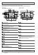
3-4. WIRED REMOTE CONTROLLER “Sensor” indication Display Section For purposes of this explanation, all parts of the display are shown. During actual operation, only the relevant items will be lit. Identifies the current operation Displayed when the remote controller sensor is used. Day-of-Week Shows the current day of the week. Time/Timer Display “Locked” indicator Shows the current time, unless the simple or Auto Off timer is set.
4 SPECIFICATIONS 4-1. SPECIFICATIONS Model 1 1 1 2 Power input Current input Heating capacity (Nominal ) 3 3 3 Power input Current input External finish External dimension H × W × D Net weight Decoration panel Heat exchanger FAN Model External finish Dimension H×W×D Net weight Type × Quantity External static press.
Model PLFY-P80VBM-E Power source Cooling capacity (Nominal) 1 1 1 2 Power input Current input Heating capacity (Nominal ) 3 3 3 Power input Current input External finish External dimension H × W × D Net weight Decoration panel Heat exchanger FAN Model External finish Dimension H×W×D Net weight Type × Quantity External static press.
4-2. ELECTRICAL PARTS SPECIFICATIONS Service Ref. Parts name PLFY-P32VBM-E.UK PLFY-P32VBM-E 1.UK Symbol PLFY-P32VBM-ER2.UK PLFY-P32VBM-ER3.UK PLFY-P40VBM-E.UK PLFY-P40VBM-E1.UK PLFY-P40VBM-ER2.UK PLFY-P40VBM-ER3.UK PLFY-P50VBM-E.UK PLFY-P50VBM-E1.UK PLFY-P50VBM-ER2.UK PLFY-P50VBM-ER3.UK PLFY-P63VBM-E.UK PLFY-P63VBM-E1.UK PLFY-P63VBM-ER2.UK PLFY-P63VBM-ER3.UK Room temperature thermistor TH21 Resistance 0 /15k , 10 /9.6k , 20 /6.3k , 25 /5.4k , 30 /4.3k , 40 /3.
Service Ref. Symbol Parts name PLFY-P80VBM-E.UK PLFY-P80VBM-E1.UK PLFY-P80VBM-ER2.UK PLFY-P80VBM-ER3.UK PLFY-P100VBM-E.UK PLFY-P100VBM-ER2.UK PLFY-P100VBM-ER3.UK PLFY-P125VBM-E.UK PLFY-P125VBM-ER2.UK PLFY-P125VBM-ER3.UK Room temperature thermistor TH21 Resistance 0 /15k , 10 /9.6k , 20 /6.3k , 25 /5.4k , 30 /4.3k , 40 /3.0k Liquid pipe thermistor TH22 Resistance 0 /15k , 10 /9.6k , 20 /6.3k , 25 /5.4k , 30 /4.3k , 40 /3.0k Gas pipe thermistor TH23 Resistance 0 /15k , 10 /9.6k , 20 /6.
4-4. NC CURVES 65.0 60.0 NC-60 55.0 50.0 NC-50 45.0 40.0 NC-40 35.0 30.0 NC-30 25.0 20.0 15.0 10.0 63 Approximate minimum audible limit on continuous noise 125 250 NC-20 500 1k 2k 4k 8k 60.0 50.0 40.0 NC-60 50.0 NC-50 45.0 40.0 NC-40 35.0 30.0 NC-30 25.0 20.0 15.0 10.0 63 Approximate minimum audible limit on continuous noise 125 250 NC-20 500 1k 2k 4k NC-40 35.0 30.0 NC-30 25.0 20.0 15.0 10.
5 4-WAY AIR FLOW SYSTEM 5-1. PLACEMENT OF THE AIR OUTLETS • For this grille, the blowout direction comes in 11 patterns. Also, by setting the remote controller to the appropriate settings, you can adjust the airflow and speed. Select the settings from Table1 according to the location in which you want to install the unit. 1) Decide on the pattern of the airflow direction.
5-2. BRANCH DUCT HOLE AND FRESH AIR INTAKE HOLE At the time of installation, use the duct holes (cut out) located at the positions shown in following diagram, as and when required. • A fresh air intake hole for the optional multi function casement can also be made. Note: The figures marked with * in the drawing below represent the dimensions of the main unit excluding those of the optional multi function casement.
5-4. FRESH AIR INTAKE AMOUNT & STATIC PRESSURE CHARACTERISTICS l PLFY-P32/40/50/63/80VBM-E.UK Multi function casement + High efficiency filter 50 50 0 0 Static pressure[Pa] Static pressure[Pa] PLFY-P32/40/50/63/80VBM-E1.UK PLFY-P32/40/50/63/80VBM-ER2.UK PLFY-P32/40/50/63/80VBM-ER3.
6 OUTLINES AND DIMENSIONS PLFY-P32/40/50/63/80/100/125VBM-E.UK PLFY-P32/40/50/63/80VBM-E1.UK PLFY-P32/40/50/63/80/100/125VBM-ER2.UK PLFY-P32/40/50/63/80/100/125VBM-ER3.
7 WIRING DIAGRAM PLFY-P32/40/50/63/80/100/125VBM-E.UK PLFY-P32/40/50/63/80VBM-E1.UK PLFY-P32/40/50/63/80/100/125VBM-ER2.UK [LEGEND] NAME INDOOR CONTROLLER BOARD CONNECTOR DAMPER REMOTE SWITCH CENTRALLY CONTROL REMOTE INDICATION FUSE (T6.3AL250V) POWER SUPPLY (I. B) POWER SUPPLY (I. B) CAPACITY CODE SWITCH MODE SELECTION MODEL SELECTION DRAIN PUMP (TEST MODE) AUX. RELAY DRAIN PUMP DRAIN PUMP DRAIN FLOAT SWITCH LINEAR EXPANSION VALVE FAN MOTOR VANE MOTOR A.B 5 6 5 5 TH22 TH23 A.
PLFY-P32/40/50/63/80/100/125VBM-ER3.UK LEGEND NAME INDOOR CONTROLLER BOARD CONNECTOR DAMPER REMOTE SWITCH CENTRALLY CONTROL REMOTE INDICATION IT TERMINAL FUSE(T6.3AL250V) POWER SUPPLY(I. B) POWER SUPPLY(I. B) CAPACITY CODE SWITCH MODE SELECTION MODEL SELECTION DRAIN-UP MACHINE(TEST MODE) AUX. RELAY DRAIN WATER LIFTING-UP MACH. SYMBOL I.
8 REFRIGERANT SYSTEM DIAGRAM PLFY-P32/40/50/63/80/100/125VBM-E.UK PLFY-P32/40/50/63/80VBM-E1.UK PLFY-P32/40/50/63/80/100/125VBM-ER2.UK PLFY-P32/40/50/63/80/100/125VBM-ER3.
9 TROUBLESHOOTING 9-1. HOW TO CHECK THE PARTS PLFY-P32/40/50/63/80/100/125VBM-E.UK PLFY-P32/40/50/63/80/100/125VBM-ER2.UK PLFY-P32/40/50/63/80VBM-E1.UK PLFY-P32/40/50/63/80/100/125VBM-ER3.UK Parts name Check points Room temperature thermistor (TH21) Liquid pipe thermistor (TH22) Gas pipe thermistor (TH23) Disconnect the connector then measure the resistance with a tester. (At the ambient temperature of 10 - 30 ) Vane motor (MV) Measure the resistance between the terminals with a tester.
9-1-1. Thermistor Room temperature thermistor (TH21) Liquid pipe temperature thermistor (TH22) Gas pipe temperature thermistor (TH23) Thermistor R0=15k' ± 3% Fixed number of B=3480 ± 2% Rt=15exp { 3480( 0: 10: 20: 25: 30: 40: 9-1-2. 1 273+t 40 Resistance (k ) Thermistor for lower temperature < Thermistor for lower temperature > 50 1 )} 273 30 20 10 15k' 9.6k' 6.3k' 5.4k' 4.3k' 3.
9-1-3. DC Fan motor (fan motor/indoor controller board) Check method of indoor fan motor (fan motor/indoor controller board) Notes · High voltage is applied to the connecter (CNMF) for the fan motor. Pay attention to the service. · Do not pull out the connector (CNMF) for the motor with the power supply on. (It causes trouble of the indoor controller board and fan motor) Self check Conditions : The indoor fan cannot turn around.
9-2.
Switch Pole SWA Ceiling height selector Effective timing Operation by switch (High ceiling) 2 (Silent) Address board = Ceiling height can be changed depends on SWB setting. 3 1~3 (Standard) PLFY-P32·P40·P50·P63·P80VBM-E 1 3 2 1 SWA SWB 4 direction 3 direction 2 direction Silent 2.5m 2.7m 3.0m Standard 2.7m 3.0m 3.3m High ceiling 3.5m 3.5m 3.
J41, J42 Wireless remote controller Pair No. Jumper Switch Pole Operation by switch • To operate each indoor unit by each remote controller when installed 2 indoor units or more are near, Pair No. setting is necessary. Pair No. setting is available with the 4 patterns (Setting patters A to D). Make setting for J41, J42 of indoor controller board and the Pair No. of wireless remote controller. • You may not set it when operating it by 1 remote controller.
9-3. TEST POINT DIAGRAM 9-3-1. Indoor controller board PLFY-P32/40/50/63/80/100/125VBM-E.UK PLFY-P32/40/50/63/80/100/125VBM-ER2.UK PLFY-P32/40/50/63/80VBM-E1.UK PLFY-P32/40/50/63/80/100/125VBM-ER3.UK CN6Y CN60 i-See sensor motor output 12VDC pulse output Linear expansion valve (LEV) output 12VDC pulse output CN3A CN4Y Connect to the terminal block (TB15) (MA-Remote controller connecting wire) 1 - 3 : 8.
9-3-2. Address board PLFY-P32/40/50/63/80/100/125VBM-E.UK PLFY-P32/40/50/63/80/100/125VBM-ER2.UK SWA SW1 Ceiling height selector Function setting SW12 Address setting 10ths digit OCH413D PLFY-P32/40/50/63/80VBM-E1.UK PLFY-P32/40/50/63/80/100/125VBM-ER3.UK SW11 Address setting 1s digit SWC SWB Discharge outlet number selector Option selector 33 SW14 Branch No.
10 SPECIAL FUNCTION 10-1. HOW TO PERFORM THE UP/DOWN OPERATION OF THE AIR INTAKE GRILLE 10-1-1. Setting up the lowering distance of air intake grille You can set up 8 different stages of lowering distance for the air intake grille according to the set up location if desired. Unit Decorative panel * As a factory default, the decorative panel will automatically stop at 1.6 m from the ceiling surface. The distance is a rough indication, check by actually lowering it.
10-1-3. How to perform the up/down operation using wired remote controller (PAR-30MAA / PAR-31MAA) 1 Select "Maintenance" from the Main menu, and press the button. Select "Auto descending panel" with the F1 or F2 button, and press the button. Maintenance menu Auto descending panel Manual vane angle Main menu: Cursor * When using the auto descending panel, always set the "Address" and "Unit No." with "Service" – "Function setting". F1 2 Move the cursor to "Ref. address", "Unit No.
10-1-4. How to perform the up/down operation using wired remote controller (PAR-21MAA) N General Operation * Raise or lower all the air intake grilles managed by the remote controller at the same time. Install the remote controller in a place where you can observe all the air-conditioners. Otherwise, the lowering grille may make contact with something and cause damage to it. 1) Ensure that the air-conditioner is not running. * The up/down operation mode is only available when the air-conditioner is "OFF".
■ Up/down operation with the individual specified air-conditioner (when used in combination with Mr. SLIM model) * Raise or lower the air intake grille of the specific air-conditioner that you select from all that are managed by that remote controller. 1) Ensure that the air-conditioner is not running. Ensure that the air-conditioner is not running. Warning: * The up/down operation mode is only available when the • Otherwise, it may cause an injury or a failure. air-conditioner is "OFF".
10-2. OPERATION (AUTO DESCENDING PANEL: PLP-6BAJ) (1) Normal operation UP/DOWN Wire 1b Air intake grille is raised/lowered by UP/DOWN UP/DOWN commands of UP and DOWN. Machine 2 Machine 1 Air intake grille does not move under the state of no-load detection or obstacle detection. Air intake grille stops automatically at the set lowering distance from the ceiling level. Detection STOP Wire 2b switch Wire 2a It stops in the cases below : • When it reaches at the set lowering distance from the ceiling level.
10-3. ELECTRICAL CIRCUIT (Controller board and wiring diagram (Panel)) 10-3-1. Dip SW 22 type SW22 LS1 BLK BLK UK1 LS21 2 1 WHT WHT Panel B O Y R R L N N W CN3G 1 2 W.B BZ SW1 FUSE CN2F (BLK) RU CN2E (RED) 2 WHT 1 WHT CN2C CN2B (WHT) (WHT) 1 2 MU1 ON SW2 1 2 1 2 LS21 SW22 1 2 3 4 5 6 7 8 9 10 CNB (WHT) 3 2 1 (BLK) CN2G (BLK) MU1 UK1 Indoor unit 3 B R L E K D 9 I.
10-3-3. Check point of trouble Turn OFF : No power supply Blink : Storage detection switch ON (short) One blink : Storage detection switch OFF (open) Two blinks : Tension detection switch OFF (open) Check item Up/down controller P.C. board supply voltage Up/down machine supply voltage Check point Normal Remarks CN3A (between 3-5) AC 198~264 V CN2B, CN2C DC 10~12 V Check when instructing up/down with LED blinking once.
11 DISASSEMBLY PROCEDURE PLFY-P32/40/50/63/80/100/125VBM-E.UK PLFY-P32/40/50/63/80VBM-E1.UK PLFY-P32/40/50/63/80/100/125VBM-ER2.UK PLFY-P32/40/50/63/80/100/125VBM-ER3.UK Be careful when removing heavy parts. OPERATING PROCEDURE PHOTOS & ILLUSTRATIONS 1. Removing the air intake grille (1) Slide the knob of air intake grille toward the arrow 1 to open the air intake grille. (2) Remove drop prevention hook from the panel.
OPERATING PROCEDURE PHOTOS & ILLUSTRATIONS Coil plate Photo 3 6. Removing the fan and fan motor (MF) (1) Remove the electrical box. (See Photo 2) (2) Remove the bell mouth (3 screws). (See Photo 2) (3) Remove the turbo fan nut. (4) Pull out the turbo fan. (5) Remove the wire cover (3 screws). (6) Remove 2 wiring clamps. (7) Disconnect the connector of the fan motor (CNMF). (8) Remove the 3 nuts and washers and rubber mounts of the fan motor.
OPERATING PROCEDURE PHOTOS & ILLUSTRATIONS 10 Removing the drain pump (DP) and float switch (FS) (1) Remove the drain pan. (See Photo 6) (2) Cut the hose band and remove the hose. (3) Remove the drain pump assembly (3 screws and 2 hooks). (4) Remove the drain pump (3 screws). (5) Remove the float switch (2 screws). Photo 8 Float switch Hose band Drain pump Drain pump assembly fixing screws Photo 9 Drain pump fixing screws 11. Removing the heat exchanger (1) Remove the drain pan.
HEAD OFFICE : TOKYO BLDG., 2-7-3, MARUNOUCHI, CHIYODA-KU TOKYO 100-8310, JAPAN cCopyright 2007 MITSUBISHI ELECTRIC CORPORATION Distributed in Dec. 2012 No. OCH413 REVISED EDITION-D Distributed in Aug. 2009 No. OCH413 REVISED EDITION-C PDF 6 Distributed in Feb. 2009 No. OCH413 REVISED EDITION-B PDF 6 Distributed in Oct. 2007 No. OCH413 REVISED EDITION-A PDF 7 Distributed in Mar. 2007 No. OCH413 PDF 7 Made in Japan New publication, effective Dec. 2012 Specifications are subject to change without notice.