
Service manual


2121
6
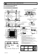
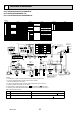
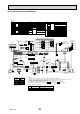
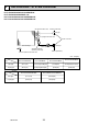
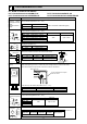
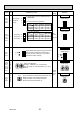
OUTLINES AND DIMENSIONS
Ceiling
Cut out hole
Burring hole pitch
3-:2.8
Burring hole
Detail drawing of fresh air intake hole
Burring hole
14-:2.8
Cut out hole
Burring hole pitch
Cut out hole
Detail connecting of branch duct(Both aspects)
100
130
350
90 100 100
90
70°
167
* 155
*
:150
:175
*
:125
:100
158
120°
120°
37728460
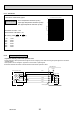
In case of auto-grille : PLP-6BAJ
In case of wireless remote controller : PLP-6BALM
In case of standard grille : PLP-6BA/PLP-6BAMD
Drain hole
Drain pump clean hole
and Drain emergency
drainage hole
Power supply wire,
Indoor unit/Outdoor unit
connecting wire entry
Indoor/outdoor unit connecting
terminal block
Emergency operation switch<Cooling>
and Emergency Up/Down switch<Up>
Emergency operation
switch<Heating>and
Emergency Up/Down switch<Down>
Control wire entry
Suspension bolt
lower edge
Vane motor
Air intake
grille
Air outlet hole
Air outlet hole
Auto vane
(Air outlet)
Air intake hole
Air intake hole
Grille
Ceiling
Keep approximately
10 to 15 mm space
between unit ceiling
and ceiling slab.
)(
Connected the attached
flexible pipe or socket.
Drain pipe
connected to VP-25
Suspension bolt
M10 or W3/8
Branch duct hole
Fresh air
intake hole
Branch duct hole
Ceiling hole
Suspension bolt pitch
Suspension bolt pitch
Ceiling hole
(7.5)(7.5)
605
620
DEFROST/STAND BY lamp
Receiver
Operation lamp
For MA-Remote controller
terminal block
160
160
1
2
500
500
597
M
M
M
M
83 36
950
8336
950
597
*
*
*
50~70
140
170
35
17
+5
0
105
156
190
A
B
*
*
*
*
160
840
150
90
C
D
840
187.5
20~45
860~910 20~45
810
20~45860~91020~45
24
160
Power supply
terminal block
Corner pocket
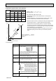
Note 1. Please choose the grille from a standard grille, auto-grille.
2. As for drain pipe, please use VP-25 (O.D. :32 PVC TUBE).
Drain pump is included.
Max. lifting height is 850mm from the ceiling.
3. As for suspension bolt, please use M10 or W3/8. (Procured at local site)
4. Electrical box may be removed for the service purpose.
Make sure to slack the electrical wire little bit for control/power wires connection.
5. The height of the indoor unit is able to be adjusted with the grille attached.
6. For the installation of the optional high efficiency filter or optional
multi-functional casement.
1) Requires E or more space between transom and ceiling for the installation.
2) Add 135 mm to the dimensions * marked on the figure.
3) The optional high efficiency filter must be used jointly with optional multi-functional
casement.
7. When installing the branch ducts, be sure to insulate adequately.
Otherwise condensation and dripping may occur.
(It becomes the cause of dew drops/water dew.)
8. As for necessary installation/service space, please refer to the left figure.
74
77
298
241 258
80
85
281
D
400
440
ECBA
Refrigerant pipe···:15.88
Flared connection···5/8 inch
Refrigerant pipe ···:12.7
Flared connection···1/2 inch
Refrigerant pipe···:6.35
Flared connection···1/4 inch
PLFY-P63,80VBM-E
PLFY-P100,125VBM-E
Refrigerant pipe···:9.52
Flared connection···3/8 inch
Models
PLFY-P32,40, 50VBM-E
Accessory ··· Drain socket (I.D. 32)
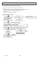
1000 mm
or more
3000 mm or
more
Indoor unit
Indoor unit
Floor
Obstacle
1500 mm
or more
Grille
Ceiling
For high
attachment
2500mm or more
from floor
Ceiling
Air intake grille
L.L Filter
Auto-grille
Max. 4.0m
Air intake grille up/down distance
PLFY-P32/40/50/63/80/100/125VBM-E.UK
PLFY-P32/40/50/63/80VBM-E
1.UK
PLFY-P32/40/50/63/80/100/125VBM-ER2.UK
PLFY-P32/40/50/63/80/100/125VBM-ER3.UK
Unit : mm
OCH413D