
Service manual


24
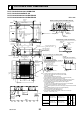
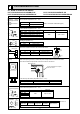
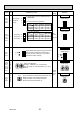
8 REFRIGERANT SYSTEM DIAGRAM
Strainer (#100mesh)
Strainer (#100mesh)
Strainer1 (#50mesh)
Strainer2 (#100mesh)
Heat exchanger
Room temparature thermistor TH21
Gas pipe thermistor TH23
Liquid pipe thermistor TH22
Linear expansion valve
Gas pipe
Liquid pipe
Flare connection
Gas pipe
Liquid pipe
PLFY-P32/40VBM-E
PLFY-P32/40VBM-E
1
:12.7(1/2)
:6.35(1/4)
PLFY-P50VBM-E
PLFY-P50VBM-E
1
:12.7(1/2)/:15.88(5/8)
:6.35(1/4)/:9.52(3/8)
PLFY-P63/80VBM-E
PLFY-P63/80VBM-E
1
:15.88(5/8)
:9.52(3/8)
PLFY-P100/125VBM-E
:15.88(5/8)/:19.05(3/4)
:9.52(3/8)
Item
Capacity
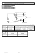
Unit : mm(inch)
Gas pipe
Liquid pipe
PLFY-P32/40/50VBM-ER2
PLFY-P32/40/50VBM-ER3
:12.7(1/2)
:6.35(1/4)
PLFY-P63/80/100/125VBM-ER2
PLFY-P63/80/100/125VBM-ER3
:15.88(5/8)
:9.52(3/8)
Item
Capacity
PLFY-P32/40/50/63/80/100/125VBM-E.UK
PLFY-P32/40/50/63/80VBM-E
1.UK
PLFY-P32/40/50/63/80/100/125VBM-ER2.UK
PLFY-P32/40/50/63/80/100/125VBM-ER3.UK
OCH413D