
Service manual


41
11
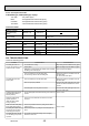
DISASSEMBLY PROCEDURE
PLFY-P32/40/50/63/80/100/125VBM-E.UK
PLFY-P32/40/50/63/80VBM-E
1.UK
PLFY-P32/40/50/63/80/100/125VBM-ER2.UK
PLFY-P32/40/50/63/80/100/125VBM-ER3.UK
Be careful when removing heavy parts.
OPERATING PROCEDURE
PHOTOS & ILLUSTRATIONS
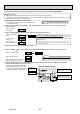
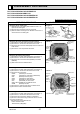
1. Removing the air intake grille
(1) Slide the knob of air intake grille toward the arrow 1 to
open the air intake grille.
(2) Remove drop prevention hook from the panel.
(3) Slide the shaft in the hinge to the direction of the arrow 2
and remove the air intake grille.
2. Removing the room temperature thermistor (TH21)
(1) Remove the air intake grille and the filter. (See Figure 1)
(2) Remove the 2 screws from the electrical box cover.
(3) Disconnect the connector CN20 (Red) from the indoor con-
troller board.
(4) Remove the room temperature thermistor.
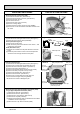
3. Removing the address board (A.B)
(1) Remove the air intake grille and the filter. (See Figure 1)
(2) Remove the 2 screws from the address board cover.
(3) Disconnect the connectors CN43 (RED/4P) and CN82
(RED/8P).
(4) Slide and remove the address board.
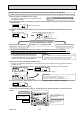
4. Removing the indoor controller board (I.B)
(1) Remove the air intake grille and the filter. (See Figure 1)
(2) Remove the 2 screws from the electrical box cover.
(3) Disconnect the connectors :
CNMF (White/7P) for fan motor
CN44 (White/4P) for thermistor (TH22/TH23)
CNP (Blue/3P) for drain pump
CN4F (White/4P) for float switch
CN01 (Black/5P) for earth and TB2
CNV (White/20P) for vane motor
CN81, CN42 (Red/8P,4P) for address board
CN2M (Blue/2P) for TB5
(4) Remove the 6 supports from indoor controller board.
(5) Remove the indoor controller board.
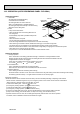
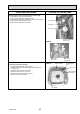
5. Removing the electrical box
(1) Remove the air intake grille and the filter. (See Figure 1)
(2) Remove the 3 screws from the electrical box cover.
(3) Disconnect the connectors. (Refer to procedure 4)
(4)
Remove 4 electrical box fixing screws and remove 2 hooks.
(5) Pull the electrical box.
<Electrical parts in the electrical box>
Indoor controller board
Terminal block (TB2) (TB5)
Filter
MA remote
controller
terminal
cover
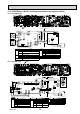
Photo 1
Electrical box cover
Terminal
cover fixing
screw
Photo 2
Electrical box
Electrical
box fixing
screws
Indoor controller
board
Electrical
box fixing
screws
Bell mouth
Room temp.
thermistor
(TH22)
Turbo fan
Electrical box cover
fixing screws
Address board
cover fixing
screw
Address
board
Address
board
cover
fixing screw
Nut
Support for Indoor
controller board
Figure 1
OCH413D