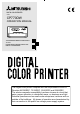
DIGITAL COLOR PRINTER MODEL CP770DW OPERATION MANUAL CP770DW PAPER FEED &CUT ALARM SHEET/PAPER SCSI COPY ONLINE DATA POWER OPEN THIS OPERATION MANUAL IS IMPORTANT TO YOU. PLEASE READ IT BEFORE USING YOUR DIGITAL COLOR PRINTER. This digital color printer complies with the requirements of the EC Directive 89/336/EEC, 73/23/EEC, 93/42/EEC and 93/68/EEC.
WARNING: In the USA or Canada, use the AC power cord according to the recommendations as below, in order to comply with UL2601-1 and CAN/CSA C22.2 No. 601.1. Case 1. Connect to the 120V receptacle of the room or the host equipment. The AC power cord should be UL or CSA approved and consist of type SJT, size 16 or 18AWG, length 2.5m or shorter cord with IEC320/C13 type, 125V 10A or higher rating connector and NEMA 5-15 type, 125V 10A or higher rating, Hospital Grade plug. Case 2.
CAUTION: RISK OF ELECTRIC SHOCK DO NOT OPEN. TO REDUCE THE RISK OF ELECTRIC SHOCK,DO NOT REMOVE COVER (OR BACK) NO USER-SERVICEABLE PARTS INSIDE. REFER SERVICING TO QUALIFIED SERVICE PERSONNEL. The lightning flash with arrowhead symbol, within an equilateral triangle, is intended to alert the user to the presence of uninsulated "dangerous voltage" within the product's enclosure that may be of sufficient magnitude to constitute a risk of electric shock.
WARNING: Install and use this appliance in accordance with the operation manual for safety and EMC (Electromagnetic Compatibility). If it is not installed and used in accordance with the operation manual, it may cause interference to other equipment and/or other risk. To prevent fire or shock hazard, do not expose this appliance to rain or moisture. This appliance must be earthed. In Europe, use the AC power cord according to the recommendations as below, in order to comply with EN60601-1 and EN60950.
INSTRUCTIONS FOR MEDICAL USE MEDICAL ELECTRICAL EQUIPMENT needs special precautions regarding EMC and needs to be installed and put into service according to the EMC information provided in the ACCOMPANYING DOCUMENTS. Portable and mobile RF communications equipment can affect MEDICAL ELECTRICAL EQUIPMENT.
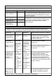
Guidance and manufacturer's declaration - electromagnetic emissions The Model CP770DW is intended for use in the electromagnetic environment specified below. The customer or user of the Model CP770DW should assure that it is used in such an environment.
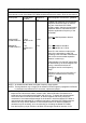
Guidance and manufacturer's declaration - electromagnetic immunity The Model CP770DW is intended for use in the electromagnetic environment specified below. The customer or user of the Model CP770DW should assure that it is used in such an environment.
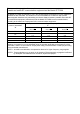
Recommended separation distances between Portable and mobile RF communications equipment and the Model CP770DW The Model CP770DW is intended for use in the electromagnetic environment in which radiated RF disturbances are controlled.
CONTENTS PRECAUTIONS 1 2-4 5 6 7-8 SPECIAL FEATURES & UNPACKING Contents ................................................................................................ Safety precautions ................................................................................ Special features .................................................................................... Unpacking ............................................................................................. Features and functions .........
SAFETY PRECAUTIONS In the interest of safety, please observe the following precautions: POWER REQUIREMENT This product is designed for operation on 100-120V AC or 220-240V AC 50/60Hz. Never connect to any outlet or power supply having a different voltage or frequency. WARNING: THIS APPARATUS MUST BE GROUNDED. AVERTISSEMENT: CET APPAREIL DOIT ETRE MIS A LA TERRE. PROTECTIVE MEASURES IF ABNORMALITIES ARISE, ....
BE CAREFUL WITH THE PRINTING MECHANISM PRECAUTIONS Do not move the printer while the printing mechanism is slid out. This may cause injury. Be careful not to catch your fingers in the printing mechanism when sliding the mechanism back into the normal closed position. CONNECTING CABLES Use the power cord supplied with the printer. When connecting the unit with an equipment with parallel data interface, use the parallel cross-over cable.
SAFETY PRECAUTIONS CONNECTING DEVICES Read thoroughly the Safety Notices, Cautions and “Operating Precautions” of the instruction booklets for the other devices connected with the unit. CAUTION ON RELOCATING When transporting this unit, make sure it is not likely to be subjected to impacts. They can be a primary cause for damage. Always use the mechanism protective cushion and the transport shipping screw when shipping the unit.
SPECIAL FEATURES SPECIAL FEATURES PRECAUTIONS 3 PRINT SIZES ARE AVAILBLE ACCORDING TO THE PURPOSE 3 printing sizes, LL size (max.150 x 104.8 mm), L size (max.130 x 104.8 mm) and S size (max.104.8 x 75 mm), are selectable. HIGH SPEED PRINTING Printing speed is approx.19 seconds (in S size print). Use of roll paper shortens the time for installing and removing. SPECIAL FEATURES & UNPACKING LARGE CAPACITY PRINTING Maximum of 200 prints per roll with S size media.
UNPACKING UNPACKING Take the unit out of the box by the following procedures. Make sure to check the contents. 1 Open the top of the box. 2 Remove the accessory box. 3 Remove the cushion above the unit. 4 Take the unit out of the box carefully. Make sure to keep the unit horizontally. Then, unwrap the packing.
FEATURES & FUNCTIONS 2 3 4 5 6 7 PRECAUTIONS FRONT PANEL 8 CP770DW ALARM SHEET/PAPER OPTION COPY SPECIAL FEATURES & UNPACKING PAPER FEED &CUT ONLINE DATA 9 POWER OPEN 1 10 7 COPY BUTTON 2 ALARM LAMP 8 ONLINE BUTTON Press to turn on power . Press again to turn of f power. When the power is turned on, the lamp above this button illuminates. When this unit is overheated, this lamp goes on and of f. When other error occurs, it illuminates. See page 18.
FEATURES & FUNCTIONS INSIDE OF PRINTING UNIT 5 4 3 2 1 1 SLIDE SWITCH 3 INK CASSETTE COMPARTMENT 4 INK CASSETTE LOCKING LEVER 5 PAPER RELEASE LEVER Load the cassette with ink sheet. Selects input PARALLEL and OPTION (SCSI) terminal input. Default setting is OPTION. When optional SCSI board is not installed, PARALLEL is selected. Push this lever to take the ink cassette out. 2 PAPER SENDING CONTROL Turn this control clockwise to rewind the print paper.
CONNECTIONS PRECAUTIONS The unit is compatible with each of the following input signals. • Parallel data signal : for Centronics compatible Parallel data interface • SCSI data signal : Refer to the operation manual of the optional SCSI board. “Centronics” is a registered trademark of Centronics Data Corporation. CONNECTION WITH PARALLEL DATA INTERFACE 2 CONNECTING WITH PC (EXAMPLE) SPECIAL FEATURES & UNPACKING Connect this unit with Personal computer as following example.
CONNECTIONS 2 SETTING ON LINE STATUS 1 2 Press POWER button to turn on this unit. • The lamp above the POWER button is lit. Turn on the power of the personal computer connected. POWER 3 Confirm that the ON LINE button on the front panel is lit. • When ON LINE is selected, the lamp illuminates. CP770DW PAPER FEED &CUT NOTE You do not need to press the ONLINE button when it is already lit. In the following conditions, ON LINE lamp illuminates when turning on the power.
PRECAUTIONS CONNECTION WITH SCSI DATA SIGNAL EQUIPMENT SCSI interface is available if optional SCSI board is installed. SCSI board is installed at the rear option slot of the unit. See the operations manual of the optional SCSI board. Make sure to turn off the power before installing the option board. (EXAMPLE) SPECIAL FEATURES & UNPACKING PC, etc. To SCSI port (When not connecting to other equipment, the terminator is required.
BEFORE OPERATION Before printing, 1. Remove the transport screw on the bottom of printing mechanism and the protective cushion. (See below) 2. Install the print paper and ink cassette. (pages 13-15) REMOVING TRANSPORT SCREW AND PROTECTIVE CUSHION To prevent damage during transportation/shipping, a protective cushion is inserted into the mechanism, and the printing mechanism is locked into position from the bottom with a transport screw. Remove the screw by the following procedures before using this unit.
2 INSTALLING MONOCHROME THERMAL PAPER PRECAUTIONS 1 Put the supplied bobbins on the both sides of the thermal paper Bobbin with gear Bobbin without gear roll. NOTE Set the bobbins as shown in the right figure. Make sure to put the bobbin on the correct position. SPECIAL FEATURES & UNPACKING 2 Unroll the thermal paper about 20cm (8 inch) and cut it not to use Incorrect sticky part. Remove the sticky part, dust, or fingerprints on the paper.
BEFORE OPERATION 3 Insert the print paper under Roller 1 and 2 in order. Roller 3 Roller 2 Roller 1 4 Insert the edge of the print paper under Roller 3. Be sure to insert the paper straight. Print paper Paper 5 Feed the print paper through the paper outlet with your hand. 6 Pull the print paper to eliminate slack. 7 Move the knob on the side of the printing unit to the direction as indicated by the arrow. NOTE If too much paper is fed,ALARM lamp may light.
NOTE When using thermal paper, do not install the ink sheet. 2 INSTALLING THE INK SHEET On the D position, turn the roller and set the notch of the roller side to the hole of the cassette. The roller can be installed when the notch is put through the hole. E B A Colored roller E D hole notch BEFORE FEATURES & CONNECTIONS FUNCTIONS OPERATION 1 Put the colored roller of the ink sheet to the ink cassette. AB 2 Put the thin stick of white roller to the ink cassette.
BEFORE OPERATION USAGE AND KEEPING OF PAPER SHEET SET 2 BEFORE PRINTING • Fingerprints or dust on the paper’s surface may degrade print quality and cause paper jams. Immediately after the paper is replaced, 2-3 images may be printed with a blank part due to hand’s dust or oil. Refer to Pages 13 - 14. • When print paper is rapidly transferred from a cool place to a hot place, vapor or dew will be generated on the paper’s surface causing paper jams or degraded print quality.
PRECAUTIONS INSTALLING PRINTER DRIVER Printer driver is required to print the data from a personal computer connected with this unit. The printer driver for Windows® is supplied with this unit. Operating conditions For Windows® Applies for Microsoft®Windows®95 and Windows®98 For Windows NT® Applies for Microsoft®Windows NT®4.0 Refer to the operation manual of the driver software or “Read me” for installing.
TROUBLESHOOTING INDICATION ON THE FRONT PANEL & COUNTERMEASURES If for some reason printing is not possible or error occurs during printing, the indicator on the front panel will be lit. In this case, follow the procedure described below. : lit : goes on and off : not lit ALARM SHEET/PAPER OPTION DATA Causes and countermeasures Page The printing unit is not inserted correctly. • Insert the printing unit until it is locked. 15 The sheet cartridge is not installed.
PRECAUTIONS OVERCOMING PAPER JAMS 1 Press OPEN button to pull out the printing unit. When it is not working, turn off the power once. Then try to press OPEN button again. BEFORE FEATURES & CONNECTIONS FUNCTIONS OPERATION Unlock the ink cassette by pushing the cassette locking lever to inside. (Refer to Page 8.) SPECIAL FEATURES & UNPACKING 2 Remove the ink cassette. 3 Turn the knob on the right side of the printing unit clockwise. Roll up the print paper completely. 4 Remove the print paper.
TROUBLESHOOTING BEFORE CALLING FOR SERVICE 2 Use the following troubleshooting chart to try to resolve any apparent defect in operation. Symptom Check and Remedy No power Is the power cord plug disconnected from the outlet? →Connect the power cord plug to the outlet firmly. →In an event of power failure, turn the power OFF and wait approx. 2 minutes to reset the power back ON. The image is not printed. Is the image data sent to this unit? →Confirm that the image data is sent to this unit.
CLEANING A small amount of alcohol Cleaning as indicated below will help maintain stable printer operation and extend the printer’s life. Preparations Cotton buds Cleaning kit (Option)* Cleaning part How to fold tissue paper Metal spatula Cleaning kit (Option) Other : Cleaner pen (Option)* *Please ask the dealer about options. SPECIAL FEATURES & UNPACKING Alcohol (isopropyl alcohol) Tissue paper (Fold in half about 4 times, and use the folded side to clean.
CLEANING 6 Cleaning paper guide shaft. The seal paste is stuck on the ditch part of the shaft if you use it for a long time. Wipe with tissue paper etc. which is soaked in a small amount of alcohol carefully . NOTE Do not touch the coated black surface with metals. Ditch part of shaft 7 Cleaning paper end sensor. Rubber roller Wipe the dust with cotton buds which is soaked in a small amount of alcohol. 8 Cleaning rubber roller. Shaft Paper end sensor The seal paste and dust etc.
SPEC & OPTIONS SPECIFICATIONS Digital Colour Printer CP770DW Printing method Sublimation Dye Thermal Transfer : 3 pass color printing (yellow, magenta and cyan) Thermal Print quality Dot resolution 325PPI Printing time Max. 1,344x 960pixels (S size) Max. 1,676x 1,344pixels (L size) Max. 1,920x 1,344pixels (LL size) PPI : Pixel Per Inch 256 (8 bits) for each color ( About 16.7 million colors) S/S-wide size L/L-wide size Approx. 19 sec./sheet (No surface coated) Approx. 27 sec.
SPEC & OPTIONS OPTIONS 2 INK SHEET Product name PK700S PK700L Ink sheet size S size L size No. of prints Usage 200 For 3 color use 130 For 3 color use Product name CK700 Ink sheet size S/L size K65H/K65HM S/L size No.
PARALLEL DATA SIGNAL 2 2 PRECAUTIONS PARALLEL DATA SIGNAL PARALLEL TERMINAL SIGNAL Pin number Connector JD36SL equivalent (36-pin) Input level TTL Parallel input connector port Signal allocation (Signal : Compatible) 36 1 18 Return pin No. Signal From/To Function 1 19 STROBE PC/VCP Strobe pulse for data reading. Incoming pulse width should be 0.5µs minimum. At regular conditions, “High” data will be read after becoming “Low”.
PARALLEL DATA SIGNAL • Parallel input connector port Signal allocation (Signal : Nibble) Pin No. Return pin No. Signal From/To 1 19 HostClk PC/VCP High 2-9 20 - 27 Unknown PC/VCP Unknown 10 28 PtrBusy PC/VCP Sends data in “Low” when HostBusy is “Low”. After HostBusy turns “High”, this signal becomes “High”. 11 29 PtrBusy PC/VCP Data4, Data8 (MSB) 12 AckDataReq PC/VCP Data3, Data7 13 Xflag PC/VCP Data2, Data6 14 HostBusy PC/VCP High : VCP is on BUSY status.
• Parallel input connector port Signal allocation (Signal : ECP) Return pin No. Signal From/To 1 19 HostClk PC/VCP Forward data transfer : Becomes “Low” when PeriphAck is “Low” and there is data to be read. Returns to “High” when PeriphACK becomes “High”.
MITSUBISHI DIGITAL ELECTRONICS AMERICA, INC. 9351 Jeronimo Road, Irvine, CA 92618, U.S.A. Phone 949-465-6000 Mitsubishi Electric Europe B.V. UK Branch Travellers Lane, Hatfield, Herts. AL10 8XB, England, U.K. Phone (0) 1707 276100 FAX (0) 1707 278755 German Branch Gothaer Strasse 8, 40880 Ratingen ; Postfach 1548, 40835 Ratingen ; Germany Phone 02102/ 486-9250 FAX 02102/ 486-7320 French Branch 25, Boulevard des Bouvets - 92741 NANTERRE cedex Phone (01) 55.68.55.00 FAX (01) 55.68.57.