
Service manual
1-
17
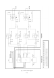
1.5 Control block
1.5.1 Function of control circuit
The control block is mainly on MAIN board and DEFL-SUB board, and the function is as follows.
(1) Auto-tracking
(2) Control of picture size, distortion and position
(3) Adjustment data memory
(4) Sync. signal detection
(5) OSM control
(6) Video pre-amp control and clamp pulse position control
(7) Power ON/OFF control
(8) Heater voltage control
(9) DDC 1 / 2B / 2Bi
(10) Operating time display
The control block is composed of the following four components.
(1) Microcomputer: IC102 (MAIN board)
(2) OSM IC: IC212 (VIDEO board)
(3) EEPROM: IC104 (MAIN board)
(4) Sync. signal input: IC215 (VIDEO board)
1.5.2 Auto-tracking process
The microcomputer (IC102) calculates the frequency of the sync. signal input and outputs the distortion
compensation data corresponding to the input signal timing to the deflection IC (IC600).
Control with IC600 is carried out via I2C bus.
1.5.3 EEPROM
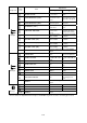
The capacity of the EEPROM (IC104) is 32 kilobits (4 kilobytes). The factory adjustment data, user
adjustment data, and EDID data are stored in the EEPROM.
Up to 9 items can be stored as the factory preset data, and up to 16 items can be stored as the user
preset data. Regarding the factory preset timing, if the user reset the memory, the factory adjustment data
will be called up.
The EDID data is stored in the last 128-byte area.
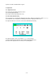
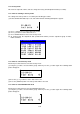
1.5.4 On-Screen-Manager (OSM) controller
The On-Screen-Manager (OSM) controller IC IC212 displays the picture used for picture adjustment and
so on. OSM display data is sent from the microcomputer (IC102) via I2C bus.
1.5.5 Heater voltage control
In the normally ON status, the heater voltage is supplied from the +8V line of the main power circuit.
Heater resistor R203H connected in series adjusts this supplied voltage to +6.15V (typ) (rated voltage for
the CRT) before application. In the suspend mode, the sub-power circuit applies the voltage so that the
screen can be instantaneously recovered. (In the suspend mode, the heater voltage is low compared with
that of the normally ON status.)
1.5.6 Protection circuit operation
This monitor can detect the following problems, and can stop the monitor operation after detection of a
problem. If the protector function is activated, the Power-On Indicator (LED) will flicker so that you can
localize the activated protector.
1.5.6.1 X-ray protector
The CRT monitor radiates X-rays, and exposure to too much radiation is very dangerous. For this reason,
the CRT monitor incorporates an X-ray protector. If the high voltage value rises above the specified value,
the protector will automatically stop applying the high voltage. For this model, the X-ray protector
activation point is set to 31.0kV (entirely black screen).
To disable the X-ray protector for the reason of repair, etc., set the monitor in the factory mode.