
Service manual


2 - 31
The luminance ratio between the center and periphery must be 80% or more with timing No. 12
(106.25kHz/85Hz, 1600x1200) COLOR 1.
The color coordination difference between the center and periphery must be ∆x, y < ±0.012
with COLOR 1.
2.5.1.17 Confirming the color tracking
Confirm with the timing No. 12 (106.25kHz/85Hz, 1600x1200), BRIGHTNESS : 7F (50%) and
COLOR1 (9300K) in factory mode.
Measure the color coordination at the center of the picture using a full white pattern (input
amplitude = 0.7Vp-p).
Confirm that the color coordination change is within the ±0.015 range when the CONTRAST is
set to 25cd/m
2
with OSM.
2.5.1.18 CRT installation position
CRT installation position tolerance
Within ±3mm in vertical direction Within ±2.5mm in horizontal direction
Inclination: Within ±2.5mm at bezel reference
2.5.1.19 Confirming SB MODE operation
Timing No.12 (106.25kHz/85Hz, 1600x1200)
Input amplitude = 0.7Vp-p (white window)
The following items should be confirmed with CONTRAST: MAX and BRIGHTNESS: 50%.
* Confirm that the color is not saturated with the white window picture during SB MODE2
operating.
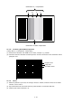
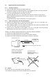
* Confirm the following items during SB MODE2 operating.
(1) Compensation of :
Confirm that A and B of the following test pattern become similar black color.
Confirm that C and D of the following test pattern become similar white color.
(2) Compensation of outline:
Confirm that the overshoot (ringing) appears on the left edge of C of the following test
pattern.
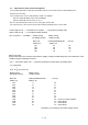
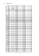
Adjustment item
Confirming
color tracking
Adjustment mode/set
Factory mode
Imput signal/pattern
No.12 : 106.25kHz/85Hz, 1600x1200
BRIGHTNESS : 7F (50%)
Status
indicator
9300K
150 or more
0.283±0.015
0.297±0.015
Approx. 0.8cd/m
2
Confirmation itemSB MODE
SB-MODE2
W-Window luminance
Back raster luminance
W-Window
color coordination
x
y