
Service manual


7-17
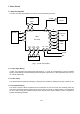
7.1.4 Contrast, White Balance, and Brightness Control
The MPU (U701) sends an 8-bit control data of contrast, white balance, and brightness to the U201 through
the I
2
C bus (SCL, SDA line). The contrast data is used for the simultaneous control of the R, G, B cathode
voltages for the three channels. The white balance data is used to control R, G, B, gains respectively. The
brightness data is used for the simultaneous control of the R, G, B bias levels. Then, the brightness data are
converted from digital to analog (DC voltage 0 to 5V) in the U201. The data from the D/A output pins (14, 15,
16) are respectively output to the bias circuits (B_BIAS, G_BIAS, R_BIAS).
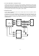
7.2 Video Bias Control
The video signals are amplified at the U204. The bias voltages output from U201 are amplified in the bias
circuit to control the Brightness.
The brightness of the back raster is adjusted by controlling the black level of the CRT cathode, which is the
DC clamp level of the output for the bias circuit. The brightness of this back raster is adjusted by the
brightness. The output from the bias circuit is dependent on the R/G/B bias and brightness. The R/G/B bias
is individually adjusted by controlling the D/A outputs from U201 Pins 14, 15, and 16 through the I
2
C bus
extended from U701.
(Fig. 7.2) Video Bias Control
BIAS circuit
U204
OUTPUT-
Amp
19
20
18
U201
Pre-Amp
7
6
9
B
G
R
1
14
16
15
2
3
B-Bias
G-Bias
R-Bias
CRT
1
2
3
B
G
R
BK
GK
RK
D254
D234
D214
R216
R236
R256
83V Line
R217
R237
R257