
Service manual


7-11
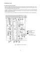
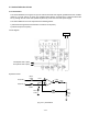
3.2.6 Linear Correction Circuit and “S” Correction capacitor Circuit
The horizontal linearity correction circuit uses a variable linear coil (T303).
The variable linear coil T303 is used to control the current with the aid of Q310, R339, C322, and C323 which
flows on the primary side of the coil.
The control signal input is entered from the drive pulse circuit of the horizontal deflection source (+B power
supply) circuit. It is dependent on the variation (input frequency and horizontal size) in the +B voltage of the
horizontal deflection circuit, and is used to control the horizontal linearity.
The “S” capacitor C517 correction circuit is enabled when all the signals are received. For the other “S”
capacitors C334, C336, C338 and C340 are turned ON and OFF at each frequency by the FETs Q315, Q317,
Q319 and Q321, respectively, in order to control the increase or decrease in the capacitance of the “S”
capacitors according to the input frequency.
The ON/OFF control of the “S” capacitors is carried out according to the CS signals (CS0, CS1, CS2 and
CS4) sent from the MPU.
(Fig. 3.2.6) Linear Correction Circuit and “S” Correction Circuit
From H_DY
+B voltage
From the
horizontal
deflection
source (+B)
circuit
Horizontal linearity
correction circuit
(variable linear coil)
+B drive
pulse input
of the
horizontal
deflection
source (+B)
circuit
“S” correction
circuit
“S”
changeover
circuit