SERVICE MANUAL FDA Series Split Systems FDA Series Multi Systems
MITSUBISHI HEAVY INDUSTRIES - PAC SERVICE MANUAL INDEX MAINTENANCE DATA 2 ERROR CODES 4 PCB INDOOR UNITS 8 ERROR DISPLAY & REMEDY CHART 12 PCB OUTDOOR UNITS 22 ERROR DISPLAY – OUTDOOR UNIT 25 OPERATIONAL DATA CHECK – WIRED CONTROLLER 35 REMOTE CONTROL – WIRED 36 - SETTING FUNCTIONS 37 ERROR DISPLAY – WIRELESS CONTROL 43 REMOTE CONTROL WIRELESS 44
1. MAINTENANCE DATA 1.1 Servicing (1) Evacuation The evacuation is a procedure to purge impurities, such as noncondensable gas, air, moisture from the refrigerant equipment by using a vacuum pump. Since the refrigerant R410A is very insoluble in water, even a small amount of moisture left in the refrigerant equipment will freeze, causing what is called ice clogging. Evacuation procedure Make sure that the both service valves of gas and liquid line are fully opened.
(2) Refrigerant charging (a) After the evacuation shown in the above, change the connection of the charge hose A to the refrigerant cylinder. (b) Purge air from the charge hose A . First loosen the connecting portion of the charge hose at the gauge manifold side and open valve 3 for a few seconds, and then immediately retighten it after observing that gas has blown out from loosened connecting portion. (c) Open valves 1 and 3 then gas refrigerant begins flowing from the cylinder into the unit.
1.3 (1) Selfdiagnosis function 1) Indoor unit side Remote controller error code Indoor unit LED Green Outdoor unit LED Cause Red Green Red Keeps flashing Stays OFF Keeps flashing Stays OFF Normal Stays OFF Keeps flashing Stays OFF Stays OFF Stays OFF Keeps flashing Stays OFF Stays OFF Power OFF, L phase wiring is open, power source failure Indoor unit microcomputer failure Keeps flashing *3 time flash Keeps flashing Stays OFF Remote controller wires X and Y are reversely connected.
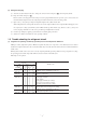
2) Outdoor unit side Remote controller error code Green Red Green Red E32 Keeps flashing Stays OFF Keeps flashing 1 time flash E33 Keeps flashing Stays OFF Keeps flashing 1 time flash Indoor unit LED Outdoor unit LED Cause Wiring is open or reversal phase (FDCA 301~601 type) Inverter primary side current is abnormal.
(b) Display sequence of error, inspection display lamp 1) One kind error Display corresponding to the error is shown. 2) More than one errors. Section Error code of remote controller Display section • Displays the error of higher priority (When plural errors are persisting) ··········· Inspection LED (red) of indoor unit PCB Inspection LED (red) of outdoor unit PCB ··········· • Displays the present errors. (When a new error has occurred after the former error was reset.
4) Recording and reset of error Error display Memory Reset Error code of remote controller • Saves in memory the mode (1) of higher priority Indoor unit inspection lamp (red) • Cannot save in memory Outdoor unit inspection lamp (red) • Saves in memory the mode (1) of higher priority Notes • Stop the unit operation by pressing the ON/OFF switch of remote controller. • Operation can be started again if the error has been reset. (1) Priority is in the order of E1 > ... > E10 > ... > E60.
Parts layout on the indoor unit PCB Model: FDT series Fan motor (151~401) ZD1 To power supply (CNW7) C41 CNV CNM3 Fan motor (501, 601) CNW9 52X8-1 KN1 52X1 52X2 52X3 C12 C13 C1 CNM2 PC3 IC8 C11 IC12 IC7 D2 F1 IC11 C58 Z2D Z3D Z4D Z5D X1 CNE IC2 IC3 C2 CNW8 R17 PC2 PC1 CNG L1 CNB Remote controller C3 SW7 C5 J1 J2 J3 J4 C4 TVS1 Connector (CNT) J5 J6 J7 J8 IC9 CNT J8 J10 J11 J12 Address switch (SW2) CNY SW8 SW5 ON J2 (SW7-2) J3 (SW7-3) J4 (SW7-4) J5 (SW8-1) J6 (SW8-2)
Model: FDEN series PCB power supply connector (Primary side) Power supply L2 CNW0 CNM1 L3 F1 52X3 52X5 IC7 IC8 CNW2 ZNR 52X2 52X4 52X6 52X2 L1 PCB power supply connector (Secondary side) Remote controller CNB CNJ2 CNM3 LED1 LED2 CNE 52X8-1 DIP switch (SW5) SW2 SW5 SW8 J5, J6 (SW8) 52X7 KN1 CNV 52X8-2 CNR Fan motor CNW1 SW10 SW9 SW7 C57 CNQ CNH CNN1 CNT J1~J4 (SW7) Connector (CNT) Heat exchanger thermistor, Return air thermistor (Thl-R1, Thl-A) J1 (SW7-1) J2 (SW7-2) J3 (S
Model: FDKN series This diagram shows the PCB for the 151~251. The component layout on the 301 PCB is different, but the functions are the same.
Model: FDUR series Heat exchanger thermistor (Thl-R2) CNH CNN1 CNN2 CNF CNB J10~J11 (SW10) CNQ SW2 SW10 CNO SW5 CNR Drain motor SW8 SW9 52X4 F1 CNG CNW2 CNM3 CNW0 PCB power supply connector (Primary side) J3 (SW7-3) J4 (SW7-4) J6 (SW8-2) With None (1) With None (1) With None (1) With None (1) With None (1) CNK2 PCB power supply connector (Secondary side) Power supply ● Control change switch (SW5, SW9, SW10) Function of DIP switch SW5 (Usually all turned OFF) ● Change by the jumper
(c) Check method when the error code is display Remote controller or Indication board: Inspection LED, error code Indoor unit PCB: Red LED (inspection display), Green LED (CPU. normal display) Outdoor unit PCB: ARed LED (inspection display), Green LED (CPU.
Indoor unit 3 time flash Keeps flashing Green LED Outdoor unit Stays OFF Keeps flashing Green LED Red LED Red LED Note (1) The green LED in the outdoor unit is used in the FDCA301 ~ 601 models only. Remote controller wiring connect check (Red· White·Black) NO Correction OK (1) Approximately 10 ~ 11 V between X and Z. NO YES NO Power supply reset Normal? Note (1) Z is GND.
2 Error display “ Red LED Green LED WAIT Indoor – outdoor communications trouble (Initial (when the power is turned on) ” Indoor unit Stays OFF Keeps flashing Red LED Green LED Outdoor unit 2 time flash Keeps flashing Notes (1) If trouble occurs during communications, the error code E5 is displayed (Outdoor, Red LED flashes 2 times). The check procedure is as shown below.
3 Error display Red LED Green LED : e1 [Communication error between remote controller~Indoor unit] Indoor unit Stays OFF Keeps flashing Red LED Green LED Outdoor unit Stays OFF Keeps flashing Note (1) The green LED in the outdoor unit is used in the FDCA301 ~ 601 models only. Voltage between X and Z approximately 10~11 V? YES Replacement remote controller Remote controller wire is removed NO Voltage fluctuates between 5~11 V between Y and Z.
4 Error display Red LED Green LED : e6 [Defective indoor unit heat exchanger thermistor] Indoor unit 1 time flash Keeps flashing Red LED Green LED Outdoor unit Stays OFF Keeps flashing Return air thermistor (ThI-A) Indoor unit heat exchanger thermistor (ThI-R1, R2) Resistance temperature characteristics Note (1) The green LED in the outdoor unit is used in the FDCA301 ~ 601 models only.
6 Error display : e8 [Heating overload] Indoor unit 1 time flash Keeps flashing Red LED Green LED Red LED Green LED Outdoor unit Stays OFF Keeps flashing Note (1) The green LED in the outdoor unit is used in the FDCA301 ~ 601 models only. YES Notes (1) Check if the overload state exists or not using the following check points.
8 Error display : Red LED Green LED [Control of 1 remote controller VS multiple units Excessive number of units (more than 17 units) ] e10 Indoor unit Stays OFF Keeps flashing Red LED Green LED Outdoor unit Stays OFF Keeps flashing Note (1) The green LED in the outdoor unit is used in the FDCA301 ~ 601 models only.
S Only case of FDKN Only case of 151~251 types Abnormal data check with remote controller After check reset, fan runs on Me. NO Fan ON? YES 3 (Black) is GND. CNM 1 and 3 (Red – Black) DC280V? NO Replacement indoor unit control PCB YES Was it reproduced? CNM 4 and 3 (White-Black) DC15V? NO Check the circumstances. YES YES 3 (Black) is GND.
10 Error display : Red LED Green LED e28 [Directive remote controller thermistor.] Indoor unit Stays OFF Keeps flashing Red LED Green LED Outdoor unit Stays OFF Keeps flashing Note (1) The green LED in the outdoor unit is used in the FDCA301 ~ 601 models only.
(4) Error diagnosis procedures at the outdoor units side At the error diagnosis related to the outdoor unit, check at first the error code of remote controller and the illumination patterns of norma1 and inspection display lamps in the same manner as the case of indoor unit. Then estimate the outline, the cause and the location of error based on the pattern and proceed to the inspcetion and repair.
Parts layout on the outdoor unit PCB FDCVA151~251 type Sub PCB (Noise filter) Reactor Fan motor Stepping motor CNM F3 CNV1 CNI2 F1 T5 T2 T1 CNW W T8 V CNL CNI3 CNTR CNI F2 T4 T7 U T6 Outdoor air temp.
S FDCA301~601 type Stepping motor PCB power supply connector (Secondary side) L6 C3 L5 C6 C5 Outdoor air thermistor, Outdoor heat exchanger thermistor, Discharge pipe thermistor (Tho-A, Tho-D, Tho-R1, 2) CNA2 C13 Outdoor unit power supplly C7 IC12 C4 C8 C1 HT1 C2 CNW CNL L7 C6 L8 SW3 C11 C9 L10 C12 LED-R CNP1 SW4 J4 J3 J2 J1 SW5 1 2 3 4 CNP2 CNV1 J16 J15 J14 J13 J12 J11 J8 J7 J6 J5 LED-G L12 L11 SW4 SW3 SW6 SW5 CNA1 C10 SW6 CNE X04 X03 X02 X07 X05 X01 X06 Cra
Outdoor Unit controller failure diagnosis circuit diagram FDCVA151~251 type ● Outdoor unit check points Check items with the *mark when the power is ON. E T24 T25 24 - TB Fuse Check: There should be continuity.
1 Error display Red LED Green LED e5 : [Communications error during operation] Indoor unit 2 time flash Keeps flashing Red LED Green LED Outdoor unit 2 time flash Keeps flashing Note (1) The green LED in the outdoor unit is used in the FDCA301 ~ 601 models only. (1) (2) Is the connection of the signal wires at the NO outdoor unit poor? Is the connection NO of the signal wires at the indoor unit poor? YES Did the remote “ controller’s LCD return to normal? Reset power supply.
3 Error display : e33 [Inverter primary current abnormal] [Only case of 151~251 type] Indoor unit Stays OFF Keeps flashing Red LED Green LED Is the power supply normal? NO Red LED Outdoor unit 1 time flash ● Display Conditions Restore it to the normal state. If the inverter’s primary current exceeds the set value for 3 sec- YES onds, the compressor stops.
Error display : Red LED Green LED e34 [Open phase at L3 phase of 52C secondary side] (Only case of 301~601 type) Indoor unit Stays OFF Keeps flashing (1) 52C secondary side L3 phase open? Red LED Green LED YES NO Outdoor unit 1 time flash Keeps flashing Notes (1) Also check if there is voltage at the L3 phase on the 52C primary side, but no voltage on the secondary side (coil wire disconnection or faulty contacts).
6 Error display : e36 [Discharge temperature error] Indoor unit Stays OFF Keeps flashing Red LED Green LED Red LED Green LED Outdoor unit 1 time flash Keeps flashing Check the unit side. During cooling: Is FM0 operating? During heating: Is FM1 operating? Are service valves (both liquid, gas) fully opened during both cooling and heating.
8 Error display : e38 [Defective outdoor air temperature thermistor] Indoor unit Stays OFF Keeps flashing Red LED Green LED Outdoor unit 1 time flash Keeps flashing Red LED Green LED Note (1) The green LED in the outdoor unit is used in the FDCA301 ~ 601 models only.
10 Error display : Red LED Green LED e40 [63H1 operation] (Only case of 301~601 type) Indoor unit Stays OFF Keeps flashing Red LED Green LED Outdoor unit 1 time flash Keeps flashing While the 63H1 is operating YES Is the 63H1 operating? NO The outdoor unit control PCB is faulty. (The 63H1 input circuit is faulty.) Replace 1. During Cooling • Is the outdoor unit fan motor running? • Is there a short circuit in the outdoor unit? • Is there enough space for inlet and outlet? 2.
12 Error display : e47 [Inverter over-voltage trouble] (Only case of 151~251 type) Indoor unit Stays OFF Keeps flashing Red LED Green LED Red LED Is there foreign matter YES such as dust or dirt on the soldered surfaces of the control PCB? Outdoor unit 1 time flash Remove the foreign matter such as dust and dirt. NO YES Is the fuse (F1: 250V, 20A) blown? Replace ● Display Conditions NO If the inverter voltage exceeds 340V, (3 times in 20 minutes), this error is displayed.
Red LED Green LED e56 [Power transistor thermistor faulty.
17 Error display : Red LED Green LED e59 [Abnormalities in compressor starting] (Only case of 151~251 type) Indoor unit Stays OFF Keeps flashing Is the power supply voltage correct proper? YES Red LED Outdoor unit 1 time, 2 time, 3 time flash Check Is the balance the compressor’s YES pressure appropriate insulation resistance during starting? and winding resistance. NO NO NG Replacement compressor Check the refrigerant level and refrigerant circuit.
Power transistor module (including drive circuit) check method Is the power transistor module cracked or burnt? NO YES Is there a short circuit between the power transistor module terminals? ❇1 NO YES Compressor operation Is the balance between the compressor current phases good? NO If there is a 10% or greater difference in the current in different phases.
(4) Check abnormal operation data with the remote controller Operation data are recorded when there is an abnormal state and these data can be displayed in the remote controller by operating the remote controller buttons. (1) Press the CHECK button. FUNCTION” → “ The display will change from “ SET ” → “OPERATION DATA button once. The display will change to “ERROR DATA (2) Press the (3) Press the SET button to enter the abnormal operation data display mode.
2 OUTLINE OF OPERATION CONTROL BY MICROCOMPUTER (1) Remote controller (a) Wired remote controller The figure below shows the remote controller with the cover opened. Note that all the items that may be displayed in the liquid crystal display area are shown in the figure for the sake of explanation. Characters displayed with dots in the liquid crystal display area are abbreviated. Pull the cover downward to open it.
(2) Setting functions using the remote controller (a) The factory settings of this unit's functions are as follows: If you want to charge a setting, follow the procedure found in the installation manual and set to your desired setting. For the method of setting, please refer to the installation manual of a remote control unit.
(b) Function setting method Operating guide message Function description: B , Settting: C 1) Stop the air conditioner Function number: A 2) Press the SET and MODE buttons simultaneously for 3 seconds or longer. The screen display will be switched as follows: Confirm Button SELECT ITEM” “ “ AUTO RUN SET SET" ON/OFF Button ” “FUNCTION SET FUNCTION SET Start Button Selector button 3) Press the SET button. The unit will enter the function setting mode.
When “I/U FUNCTION ” is selected. 1 The screen display will be switched as follows: “ SET” “I/U No.00” (blinking) I/U SELECT” “ I/U No.00 or button. 2 Press either Select the indoor unit number that you want to change settings. If only one indoor unit is connected, the indoor unit number will not charge, so please proceed to Step 3. If “ALL I/U ” is selected while indoor group control is in effect, you can set all units to the same settings. 3 Press the SET button.
(d) Changing the remote controller’s temperature setting range 1) The temperature setting range of the remote controller can be changed. Through remote controller button operations, the upper limit and lower limit set temperature values can be changed individually. During heating operation, the changed upper limit value becomes valid and at times other than during heating operation, (during cooling, dehumidification, auto and fan operation), the changed lower limit value becomes valid.
(3) Cooling Test Operation Procedure Carry out the following test operation procedure using the remote controller. (a) Starting the Cooling Test Operation 1 Press the ON/OFF button to start operation. 2 Press the MODE button and select “COOL.” 3 Press the TEST button continuously for 3 seconds or longer. The display changes from “ 4 When “ TEST RUN SELECT ITEM” “ SET" “ TEST RUN .” ” is displayed, press the SET button to begin the cooling test operation. The display shows “ TEST RUN.
(5) Test run (a) Test run method 1) A test run can be initiated from an outdoor unit by using SW9 (SW2) and SW5-4 for on-site setting. 2) Models FDCVA151~251 When SW9 (press button switch) is pressed for 1 second and then released, the compressor will start operation approximately 5 seconds later. Models FDCA301~601 Press SW2 (push-button switch) for one second. The compressor will start when the button is released. The compressor will stop when 30 minutes elaps.
3. Check display on wireless specification models (FDTN · FDEN · FDKN) (1) Indication board (a) FDEN Series Romote controller signal receiving part Backup switch TIMER CHECK RUN Operation display light (Green) • Lights continously: Under air conditioner operaton • Keeps flashing: Under heating preparation (At the time of heating operation) • 3 time flash: Under reception of a remote controller signal Timer/Check display light (Yellow) • Lights continously: Under timer operation • 0.5 second lighting,0.
(c) Wireless remote controller Signal sender OPERATION MODE indicator Signals are sent to the air conditioner from here. Indicates selected operation mode Filter reset indicator Fan speed The FILTER mark is indicated when the FILTER RESET button is pressed. Indicates the selected fan speed Auto swing Indicates the selection of swing louver. Temperature indicator AUTO COOL DRY FAN HEAT FAN HI ME LO °C Timer ON time Indicates the timer ON time.
NOTICE The installation of this equipment must NATIONAL, STATE and LOCAL CODES. comply with all This Service Guide does not cover all installation circumstances and is meant for guidance only and therefore will not form part of any legally binding contract. An installation guide is provided with the air conditioning equipment.