
Service manual


-
8
-
CNM3
52X6 52X1 52X2 52X3
52X4
52X8-2
PC3
IC2
C2
X1
CNE
F2
F1
Z2D
Z3D
Z4D
Z5D
R16
ZD1
CNJ
D2
IC7
TVS1
CNM2
CNW8
CNT
IC9
J8
1234
J10
J11
J12
CNR
IC12
CNG
LED2
LED1
CNW9
C13
PC5
C12
C1
L1
C58
IC3
C4
C3
CNY
CNI
CNH CNN1
SW2
SW10
SW5
1234
SW7
J5
J6
J7
J8
SW8
J1
J2
J3
J4
SW9
IC11
IC8
CNB
C11
C41
KN1
CNV
52X7
52X8-1
CNW7
TM1
PC2 PC1
R17
C23
L2
ON
ON
C5
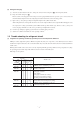
Fan motor
(501, 601)
Power supply PCB
(CNW8)
Connector
(CNT)
Address switch
(SW2)
Heat exchanger thermistor,
Return air thermistor
(Thi-R1, Thi-A)
Heat exchanger
thermistor
(Thi-R2)
J9~J11
(SW10)
DIP switch
(SW5)
J5~J6
(SW8)
DIP switch
(SW9)
J1~J4
(SW7)
Remote
controller
Louver motor
To power supply
(CNW7)
To power supply PCB
(501, 601) (CNW9)
Fan motor
(151~401)
Parts layout on the indoor unit PCB
Model: FDT series
Input signal - Reverse invalid
Input signal - Rus stop
Heating thermostat OFF-Lo
Heating thermostat OFF-Stop, Lo
Normal operation operable
Operation permission prohibited
Normal
Heating temp. +3
Louver free stop control - Invalid
Louver free stop control - Effective
Freeze prevention fan control activated.
Freeze prevention fan control deactivated.
J1 (SW7-1)
J2 (SW7-2)
J3 (SW7-3)
J4 (SW7-4)
J5 (SW8-1)
J6 (SW8-2)
With
None
(1)
With
None
(1)
With
None
(1)
With
None
(1)
With
None
(1)
With
None
(1)
Name Function
Note (1)
(2)
“None” means that jumper wire is not provided on the PCB or the
connection is cut
The replacement board is not equipped with jumpers J1 ~ J6. Instead,
SW7 and 8, with the same functions as jumpers J1~J6, are used in the
position where the jumpers were previously. Set SW7 and 8 locally in
accordance with the above table.
Note (1) It is normally ON only in the case of SW9-4.
Setting time : 1000hrs. (Unit stop)
Setting time : 1000hrs. (Display)
Setting time : 600hrs. (Display)
Setting time : 180hrs. (when shipped from factory)
SW5-4SW5-3
ON
OFF
ON
OFF
ON
OFF
Switch Function
Emergency operation
Normal
Fan control : Powerful mode
Fan control : Mild mode
SW9-3
SW9-4
SW10-1 (J9)
Switch Function
Auto swing fanction - None
Auto swing function - With
Remote controller air flow –
Remote controller air flow 1 speed
Remote controller air flow 2 speed
Remote controller air flow 3 speed
SW10-3
(J11)
SW10-2
(J10)
OFF
ON
OFF
ON
OFF
ON
OFF
ON
ON
OFF
ON
OFF
Switch Function
● Control change switch (SW5, SW9, SW10)
Function of DIP switch SW5 (Usually all turned OFF)
Function of DIP switch SW9 (Usually all turned OFF)
● Change by the jumper wire
Function of DIP switch SW10 (Usually all turned OFF)