
Specifications


APPENDIX 3 CABLE MANUFACTURING DRAWINGS
I-24
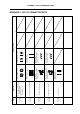
<Cable type name table>
Appendix No. Cable type Application Max. length Standard cable length
Appendix 3.1 R000 cable Encoder : 2ch 30m
Appendix 3.2 R211 cable Remote I/O
∗50m
Appendix 3.3 R220 cable +24V input 30m
Appendix 3.4 R300 cable DI/DO 20m
Appendix 3.5 R301 cable DI/DO 20m
Appendix 3.6 R-TM terminator RIO unit communication terminator
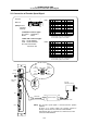
(Note 1) For the cable with an asterisk (∗) in the maximum cable length column, the total length (L1+ L2 + L3) of the cable length
(L1) from the control unit to the base I/O unit, the cable length (L2) from the base I/O unit to this unit, and the cable
length (L3) from this unit to each unit must be less than this value.
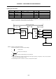
R211
Control unit
Base I/O unit
Maximum cable length
RIO1
ENC1
ENC2
F010
Servo amplifier
Remote I/O unit
Encoder
L2
L1
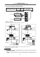
R300/
F301
F050
Expansion
I/O unit
RIO1
RIO2
L3
R211
R000
Remote I/O unit
(FCU6-DX561)
DI-L/-R
DO-L
Machine operation panel
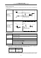
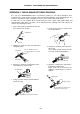
(Note 2) Symbols for writing cable drawings
The following symbols are used in the cable drawings.
1.
indicates twist.
2.
indicates the shield sheath.
3.
indicates shield clamping to the ground plate.
4. In the cable drawings, the partner of the twisted pair cable is given a priority, so the pin Nos. of the connectors at both
ends are not necessary in number of order.
5. Equivalent parts can be used for the connector, contact and wire material.