MITSUBISHI HEAVY INDUSTRIES, LTD.
INDEX Chapter 1 Foreword Chapter 2 Arm designation and motion 2.1 2.2 2.3 2.4 2.5 Axis designation Coordinate system Coordinate system creation Rotation direction on coordinates Transformations Chapter 3 Control Mode 3.1 3.2 3.3 3.4 3.5 Motion control mode Trajectory control mode Axis angle interpolation RMRC tip interpolation Velocity control Chapter 4 Motion and operation control section 4.1 Motion control section 4.2 Operation control section 4.3 Operation and motion control section interface Chapte
Chapter 6 Programming 6.1 Control arm 6.2 Common items 6.3 Axis angle Control 6.3.1 Axis angle Control 6.3.2 Axis orientation Control 6-1 6-2 6-3 6-7 6-8 6-9 6.4 Tip position / orientation (RMRC) control: 6 (six) axis arm 6.4.1 Tip position / orientation (RMRC) control 6.4.2 Motion in peculiar orientation ( at a peculiar point ) 6.4.2.1 Types of peculiar points 6.4.2.2 Singularity avoidance motion 6.4.2.3 Control around angle limit 6-11 6-11 6-19 6-20 6-21 6-23 6.5 Tip position / orientation (RMRC) cont
PA10 Series Programing Manual SKC-GC20002 Rev.0
chapter 1. FOREWORD Chapter 1. Foreword This is the programming manual of the new concept robot “Mitsubishi heavy Industries, Ltd. – General Purpose Robot: PA” to be employed in various ways for a wide range of customers. The “PA” has two controllers: at the operation and motion control section. At the operation control section, the C- language library (PA library) is provided to access the motion control section. This manual explains how to use this “PA library” in C and BASIC language.
Chapter 2. ARM DESIGNATION AND MOTION Chapter 2.
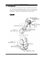
Chapter 2. ARM DESIGNATION AND MOTION 2.1 AXIS DESIGNATION Joint structure, axis designation and motion of “Mitsubishi heavy Industries, Ltd. – General Purpose Intelligent Robot PA” are shown in the drawing below. It might have a difference between configuration of the actual machines and this illustration. However, the coordinate system is the same to both.
Chapter 2.
Chapter 2. ARM DESIGNATION AND MOTION 2.2 COORDINATE SYSTEMS In manipulator control, to indicate the current position/orientation and the target position/orientation, the standard coordinate system is needed. Inputting the deviation of position and orientation (rotation angle on the standard axis) for coordinates they can be controlled. The coordinate systems used in the motion controller are as follows: ・Base Coordinates ・・The manipulator origin is the basic standard.
Chapter 2. ARM DESIGNATION AND MOTION 2.3 COORDINATE SYSTEM CREATION How should the coordinate system shown in the section 2.2 be created: Here it is explained how to assign coordinate to each link which constructs a manipulator. 【joint coordinate】 1e 1b 1w 1s z7 W2 W1 z1 z3 z5 E2 E1 S3 S1 S2 z2 x 1 z4 z6 p z a (0,0,0) Z Base Coordinate Mech.
Chapter 2. ARM DESIGNATION AND MOTION (1)Base Coordinate Systems The base coordinate is the origin of a manipulator.
Chapter 2. ARM DESIGNATION AND MOTION (2)Mechanical Interface Coordinates Mechanical interface coordinates (tool tip coordinate) will be created as follows: ・First of all, create the conversion matrix A1 from the manipulator origin, indicating the S1 origin. →The coordinate of S1 origin located at base coordinate: T1=T0A1 ・Then, create conversion matrix: A2 indicating the S2 origin for the S1 origin (T1 coordinate.
Chapter 2. ARM DESIGNATION AND MOTION 2.4 ROTATION DIRECTION FOR COORDINATE SYSTEMS Input values for each coordinate as follows.
Chapter 2. ARM DESIGNATION AND MOTION 2.5 CONVERSION Space conversion with a 4x4 Matrix can indicate the conversion of translation and rotation. Using these conversions and coordinates, they designate the position and orientation of a manipulator. (1)Position designation Position designation (conversion) is to translate X, Y and Z directions of the basic coordinate T.
Chapter 2.
Chapter 3. CONTROL MODE Chapter 3. CONTROL MODE Looking at the nearest point to H/W in the manipulator control, command values are given to each axis. As the actual operation method, not only makes each axis move, but also needs complex movements controlling orientation or the tip position to be straight.
Chapter 3. CONTROL MODE 3.1 ACTUATING CONTROL MODE Actuating control methods for PA, are provided as follows: Also data interpolation will be performed when it operates for all modes.
Chapter 3. CONTROL MODE (1)Axis angle Control Operation method ordering each axis target angle or previously defined each axis value, through the operation controller. Reference Programming is explained in Section 6-3. (2)Tip Position /Tip Orientation Control Method to shift the tip straight or rotate the tip direction by inputting the tip position/orientation deviation for the defined coordinate axis by the operation controller.
6.11 Playback Control 6.11.1 PTP linear interpolation data and playback control 6.11.2 PTP arc interpolation data and playback control 6.11.3 PTP circle interpolation data and playback control 6.11.4 PTP axis interpolation data and playback control 6.11.5 Teach data playback control mixed with various data 6.11.6 Differences between current point operation and playback control 6.11.7 JUMP rules 6-84 6-85 6-86 6-88 6-89 6-91 6-92 6-94 6.12 Tip Offset Control 6.12.1 Coordinate conversion matrix control 6.12
Chapter 3. CONTROL MODE (7)Real-Time Control This mode controls the arm in position/orientation or each axis angle, at actual time, inputting tip position/ orientation or each axis angle every control cyclic time. The command ( tip position/orientation Matrix or each axis angle every control cyclic time) has to be issued every time-out. Reference Programming is explained in the section 6.8.
Chapter 3. CONTROL MODE (5)Direct Control (Optional function) After switching on the torque control and releasing the brake, this direct control is for the manually arm operation mode. This control mode memorizes each axis data as the teach (PTP) data when an arm is operated manually. It revives the movements through the playback control. ・Simple weight compensation control Reference Programming is explained in section 6-7.
Chapter 3.
Chapter 3. CONTROL MODE 3.3 Axis Angle Interpolation Here is the explanation for each axis angle control in the trajectory control mode. Each axis angle control <Input value> target angle(θrS1,θrS2,・・θrW2) <Calculation> ① Calculate deviation angle and subtract the current value from the target one, at each axis. θrS1 - θcS1 ΔθS1 ΔθS2 = θrS2 - θcS2 : : ΔθW2 θrW2 - θcW2 .
Chapter 3. CONTROL MODE 3.4 RMRC Tip Interpolation The method to shift a manipulator tip position/orientation to the next target position/orientation in the trajectory control mode is explained here. Tip position/orientation interpolation methods currently provided in PA10 are three as follows: ・Linear Interpolation ・・・The tip trajectory is straight. The tip orientation is concurrently interpolated, too. ・Arc Interpolation ・・・The tip trajectory is an arc.
Chapter 3. CONTROL MODE (1)Linear interpolation Tip orientation rotation angle: e interpolation Pr Pc Tip position shifting value: L <When the redundant axis control mode is NOT “S3-axis restriction” and “S3-axis interpolation mode in 6-axis and 7-axis arm> 1. 2. 3. 4. 5. 6. 7. OUTLINE PROCEDURE FOR LINEAR INTERPOLATION Calculate the current tip position and the tip orientation (Tc). Calculate the target tip position and the tip orientation (Tr).
Chapter 3. CONTROL MODE (2)Arc & Circle Interpolation Arc Interpolation Circle Interpolation Tip Shifting Direction P2 θ1 P1 P1 θ1 P3 0 r 0 Vec P3 P2 r Vec P3 Orientation Rotation A θ P1 Orientation rotation Angle:θ2 = 0 Position Shifting rotation Angle: θ1 = 2π <When the redundant axis control mode is NOT “S3-axis restriction” and “S3-axis interpolation mode in 6-axis and 7-axis arm> 1. 2. 3. 4. 5. 6. 7. 8. 9. 1. 2. 3. 4. 5. 6.
Chapter 3. CONTROL MODE 7. Calculate rotation angle (θS3) if S3-axis orientation from the S3-axis angle, of the current value (P1) and the S3-axis angle of the target value (P3). In the case of the circle, it is (θS3) = 0.0 [rad] ( in the case of circle interpolation, S3-axis DOES NOT move and make the same motion as “S3-axis fixed”. 8. To operate the position and the orientation, the standard for interpolation must be chosen from the position, the orientation or the S3-axis. 9.
Chapter 3. CONTROL MODE 3.5 Velocity Control When a manipulator plus a machine operator perform, if, command value is given intermittently, it causes undesirable mechanical oscillation. For this reason, the command speed at the start has to be controlled, to gradually accelerate and at stop to gradually decelerate. On manipulator trajectory, velocity is generally controlled to make a trapezoid wave. With this trapezoid wave, the acceleration wave becomes non continuous.
Chapter 4 Chapter 4.
Chapter 4 Motion & Operation Control Section 4.1 Motion Control Section The motion control section – the controller handles the basic control for PA – operates following each control mode explained in chapter 3. The limitation cycle is 2ms. Regarding the program for this section, as long as PA is employed, even if the operation contents are changed, the program remains the same.
Chapter 4 Motion & Operation Control Section 4.2 Operation Control Section The operation control section – the controller handles the operation procedures. The program for this section changes depending on the operation: (on each application: weddings, painting, etc) The standard software for PA: the operation support program (man- machine) and PA Library (the motion and control section and interface section) are provided. The motion control board is compatible with PCI bus.
Chapter 4 Motion & Operation Control Section 4.3 Operation & Motion Control Section Interface The Operation section and the Motion Control section are connected by PCI bus. The memory area is shared at the PCI space. The operation control section sets the target command (event) to this memory area. The motion control section operates following a event. The arm movement can be observed at actual time.
Chapter 5 Chapter5 Program Development & Processing Conditions Program Development & Processing Conditions 5- 1
Chapter 5 Program Development & Processing Conditions 5.1 Development & Processing Conditions For processing conditions, if you intend to provide your own operation control section (Personal Computer), you must need the following: ・OS :Windows NT/2000/XP ・Memory :More than 128 MB Further more, for development, the following are needed. ・Compiler:Visual C++ Compiler Ver.6.0 or Visual BASIC Compiler Ver.6.
Chapter 5 Program Development & Processing Conditions 5.3 PA library Directory Composition The PA library is provided by the CD-ROM. When the CD-ROM is set, installation starts automatically. (For further information, refer to the installation manual.) Reference The PA library compositions provided in PA are as follows: \ WinPApci (Default name of installation destination) BIN ••• Execution file Passage.exe Wprm.exe INCLUDE ・・・ Header file of PA library PA.
Chapter 5 Program Development & Processing Conditions SAMPLE MFC EX1 ••• Sample program employing MFC EX1.CPP EX1.ICO EX1.H EX1.RC2 EX1.RC EX1DLG.CPP EX1DLG.H RESOURCE.H STDAFX.CPP STDAFX.H EX1.DSW EX1.DSP VC EX1•••Sample program employing VisualC++ DLGPROC.CPP MAIN.CPP RESOURCE.H EX1.RC EX1.DSW EX1.DSP EX1.EXE EX2•••Sample program employing VisualC++ DLGPROC.CPP MAIN.CPP RESOURCE.H EX2.RC EX2.DSW EX2.DSP EX2.EXE VB EX1•••Sample program-1 employing VisualBasic MAIN.BAS DEFINE.BAS FUNC.BAS AXISOPE.
Chapter 5 Program Development & Processing Conditions Additionally, if the operation support software is purchased together, the following files are installed into the system directory. CMCTLJP.DLL MSSTDFMT.DLL msvcrt.DLL scrrnjp.DLL Scrrun.DLL STDFTJP.DLL MSCMCJP.DLL MSCOMJP.DLL MSCOMM32.ocx MSCOMCTL.ocx Remark ・ Files needed to develop an application program for the operation control section employing Visual C++ (Ver.6.0) are the following, indicated on gray background: PA.H PAERR.H PAPCI.LIB PAPCI.
Chapter 5 Program Development & Processing Conditions 5.4 Notes for application development employing Visual C++ (1)Header files are needed to be included. Using the PA library, if an application program is developed employing Visual C++ ver.6.0, the following header files have to be included. (using MFC, likewise.) PA.H ・・・・ PA library prototype declaration is described. PAERR.H ・・・・ PA library error code declaration is described.
Chapter 5 Program Development & Processing Conditions (3)Structural Member Alignment Alteration Structural member alignment has to be set for 2 bytes. (default is 8 bytes) Choose “Setting…” inside “Project” of the menu bar, then choose “code creation” in the C/C++ category, then, change the structural member alignment for 2 bytes.
Chapter 5 Program Development & Processing Conditions 5.5 Notes for application development employing Visual BASIC (1)Necessary header files to include Using the PA library, if develop an application program employing BASIC ver.6.0, add the following header files. (the standard module file) to the “project.” PA.BAS ・・・・ The prototype declaration is described when load the PA library created with C-programming language employing BASIC.
Chapter 6 Programming Chapter 6 Programming How to create an application using the PA library.
Chapter 6 Programming 6.1 Control Arm (1)6-axis and 7-axis arm The PA library for 6-axis and 7-axis is described as the same. Some libraries can only be used for the 7-axis arm, not for the 6-axis one. A processable library inter-lock is checked at the motion control side. For the 6-axis arm, on command values to each axis, the S3-axis (configuration [2]) value becomes invalid. (example) Axis value Velocity command Value Type Declaration ANGLE axis axs.S1 axs.S2 axs.S3 axs.E1 axs.E2 axs.W1 axs.
Chapter 6 Programming 6.2 Common Items On the control programming using the PA library, there are some that must be known and followed through. (1)Synchronization between controllers One command is issued for one PA library from the operation control section to the motion control section. The motion control section performs the motion/processing, responding to this command. Synchronization between controllers is operated by the control counter.
Chapter 6 Programming Explanation on the programming employing samples. ・ Example: for Visual C++ – the one written with the visual C++6.0 programming language is indicated. ・ It is the same as other C-programming language (either Windows or not) ・ Example: for Visual BASIC – the one written with the visual BASIC programming language is indicated. Remark In the sample, making easier to understand the description method, function return values ARE NOT checked.
Chapter 6 Programming (3)Processing during a library performance Explaining processing methods while a library describing motion is performing. func = WM_WAIT :Wait until the arm motion is terminated. = WM_NOWAIT:No wait until the arm motion is terminated. func = WM_WAIT : Wait until the arm motion is terminated <Library Processing Contents> ・Issues command to the motion control section. ・Observes the motion termination. ・If any error occurs, terminates processing.
Chapter 6 Programming func = WM_NOWAIT : No wait until the arm motion is terminated <Library Processing Contents> ・Issues commands to the motion control section. ・If any error occurs, terminates processing. An error number is shown as a return value. ・Confirmation and error observation are not performed at the motion termination. Example: for Visual C++ long new, old; long err; : pa_get_cnt(ARM0, &old); ...
Chapter 6 Programming 6.3 Axis Angle Control Method to control from the operation control section providing axis target angle. The motion control section calculates each axis interpolation and controls angle Current angle of axis feedback.
Chapter 6 Programming 6.3.1 Axis Angle Control Designates axes to be controlled and provides target angles. Program Description:: Example: for Visual C++ To control only S1,S2 and E1 at 90 [deg] : ANGLE angle; : angle.s1 = 1.57; (= 90.0 * M_PI / (double)180.0) angle.s2 = 1.57; angle.e1 = 1.57; pa_exe_axs( ARM0, S1|S2|E1, & angle, WM_NOWAIT ); Example: for Visual BASIC : Dim ret As Long Dim axs As Long Dim agl As ANGLE : agl.s1 = 1.57 agl.s2 = 1.57 agl.e1 = 1.
Chapter 6 Programming 6.3.2 Axis Orientation Control This control method is the same as the axis control. ・Basic Orientation All Axes :0 [deg] ・Escape Orientation S2 :30[deg] E1 :90[deg] W1 :60[deg] Others: 0[deg] ・safety Orientation S2 E1 W1 Others : 45[deg] : 90[deg] :-45[deg] : 0[deg] Alteration methods for each orientation angle are: ・Method to input the angle. ・Method to replace with a current angle. These values are erased when the power is off. default value, use the parameter setting program.
Chapter 6 Programming Example: for Visual BASIC Dim agl As ANGLE Dim ret As Long Dim axs As Long ret = pa_exe_esc( ARM0, WM_NOWAIT ) to the default escape orientation. agl.s1 = 1.57 agl.s2 = 1.57 agl.e1 = 1.57 : agl.w2 = 1.57 ret = pa_set_esc( ARM0, agl ) escape orientation alteration ret = pa_exe_esc( ARM0, WM_NOWAIT ) all axes to 90[deg] : agl.s1 = 0.785 agl.s2 = 0.
Chapter 6 Programming 6.4 Tip Position/Orientation (RMRC) Control: 6-axis arm The following explanation about the tip position/orientation control for the 6-axis arm is the summarized one. For the 7-axis arm, it is explained in the section 6.5. 6.4.1 Tip Position/Orientation (RMRC) Control PA10 tip position/orientation (RMRC) control is the method to control arm providing its tip position/orientation as the target value from the operation control section.
Chapter 6 Programming Tip Position/Orientation Interpolation Method This method calculates the tip position/orientation interpolation and controls the tip to the input target position/orientation. This method interpolates the velocity command to form a letter “S” shape. The motion velocity, adjusting to the position/orientation default velocity, is interpolated to form a letter “S” shape.
Chapter 6 Programming (1)Tip Position Deviation Control Position deviations (ΔX,ΔY,ΔZ) from the current tip position are provided to each axis in the selected coordinate system. ・Base coordinate tip position control:pa_mov_XYZ( ARM0, dX, dY, dZ, WM_WAIT ) ・Mechanical interface coordinate tip position control:pa_mov_xyz( ARM0, dx, dy, dz, WM_WAIT) ( Visual BASIC: pa_mov_XYZ0( ARM0,dx,dy, dz, WM_WAIT ) ) In Visual BASIC, there is no distinction between capital and small letters.
Chapter 6 Programming (2)Tip Orientation Deviation Control Orientation deviations (ΔYaw,ΔPitch,ΔRoll) from the current tip orientation are provided to each axis in the selected coordinate system.
Chapter 6 Programming Example: for Visual C++ : pa_exe_esc(ARM0,WM_WAIT); pa_mov_ypr(ARM0,0.0,20.0*PI/180.0,0.0,WM_WAIT); ・・・ (a) : A 20[deg] rotation on Y-axis in the mechanical interface coordinate system : pa_set_tol(ARM0,0.0,0.0,0.0,0.0); ・・・ Set tool offset (float type) pa_mov_ypr(ARM0,0.0,20.0*PI/180.0,0.
Chapter 6 Programming (3)Designated Absolute Position/Orientation Control The tip matrix (T-matrix) on the base coordinate system and each axis value for restriction data are provided. nx ox ax px T-matrix : ny oy ay py nz oz az pz Target matrixes are as follows: ・Absolute position target matrix: controls only positions and orientation does not change. ・Absolute orientation target matrix: controls only orientation and positions do not change.
Chapter 6 Programming Program Description: ① Adjusts the axis value to the RMRC controllable one.: pa_exe_saf The possible start range for RMRC control is limited. The entry to the RMRC control is not allowed when E1=0[deg]. The entry to the RMRC control from the basic orientation is not allowed. One of the ways to enter the RMRC control is to shift to the safety orientation. ② The tip position/orientation matrix described in the base coordinate system is provided.
Chapter 6 Programming (4)Tip Position/Orientation/velocity Control Method to control providing linear motion velocity (Vx, Vy, Vz) and rotational velocity (Vyaw, Vpitch, Vroll.) on each coordinate axis in the selected coordinate system Reference For further information, refer to “Velocity Control” in the section 6.6 (5)Current Point Motion Control (Tip Linear motion) Shifts, interpolating the tip position/orientation linearly with the RMRC control to the current point.
Chapter 6 Programming 6.4.2 Motion at the singular posture (singularity) Awareness on RMRC control operation. In RMRC control, arm is usually actuated by providing commands to the tip position and orientation of the manipulator, calculating joint angle velocity to actualize. CAUTION When the tip takes a position/orientation called a singularity, to maintain a consistent tip trajectory and motion velocity, it is needed to instantly increase some joint velocity.
Chapter 6 Programming 6.4.2.1 Singularity types On singularity, there are three inner singularities (wrist, elbow and shoulder singularity) and the outer singularity located out of the arm movable range. <Inner Singularity> Inside the arm movable range, the position/orientation cannot be controlled when a joint angle is exceeded, or lowers the control accuracy. Wrist Singularity…Rotational axes of E2 and W2-axis are linear. = W1-axis is 0 (E2 and W2-axis are indeterminate.
Chapter 6 Programming 6.4.2.2 Singularity Avoidance Motion Singularity avoidance algorism in PA10 customized on the basis of the SC (singularity – Consistency) method discoursed by Professor Tsumaki, Tohoku university. Its outline is explained below. If needed exceeding velocity to any axis during RMRV control, the SC method – the algorism – lowers the tip velocity and maintains its position and posture. During RMRC control, in PA10, the operation is always controlled by the SC method.
Chapter 6 Programming Around a singularity it is not always possible to make all avoidance motions. At a singularity below, arm stops in error. <Wrist Singularity> Around the wrist singularity, in unstable areas, the velocity command sends an error signal to the brake to stop. <Elbow Singularity> Exceeded arm length: If E1-axis passes through 0[deg] (the length from S2 rotation origin to W1 rotation origin: 930 [mm],) the RMRC control is not allowed to enter.
Chapter 6 Programming 6.4.2.3 Control around Angle Limit Entry protection to the angle limit: The SC method is the algorism built-in originally for singularity avoidance. In PA10, using this algorism, processing to decelerate the whole motion of a manipulator just before the angle limit. Conditional analyses are performed to all moving axes. If any of them approaches to the angle limit, it is forcefully decelerated following SC method.
Chapter 6 Programming 6.5 Tip Position/Orientation (RMRC) Control: 7-axis arm The tip position/orientation control for the 7-axis arm is as follows: 6.5.1 Tip Position/Orientation (RMRC) Control PA10 tip position/orientation (RMRC) control method to control arm providing its tip position/orientation as the target value from the operation control section. The motion control section calculates interpolation of each tip position/orientation and controls the position feedback.
Chapter 6 Programming In 7-axis arm, the tip position/orientation (RMRC) control can be classified in two on a large scale. ① Elbow control changing the tip position/orientation.
Chapter 6 Programming 6.5.2 Elbow Control changing the tip position/posture (1)Tip Position Deviation Control Position deviations (ΔX,ΔY,ΔZ) from the current tip position are provided to each axis in the selected coordinate system.
Chapter 6 Programming (2)Tip Orientation Deviation Control Orientation deviations (ΔYaw,ΔPitch,ΔRoll) from the current tip orientation are provided to each axis in the selected coordinate system. ・Base coordinate tip position control:pa_mov_YPR(ARM0, dYaw,dPitch,dRoll,WM_WAIT) ・Mechanical interface coordinate tip orientation control: pa_mov_ypr(ARM0,dyaw,dpitch,droll, WM_WAIT ) (In the case of Visual BASIC: pa_mov_YPRO(ARM0,dyaw,dpitch, droll, WM_WAIT) ) Control Method: ・The tip position does not change.
Chapter 6 Programming Example: for Visual C++ : pa_exe_esc(ARM0,WM_WAIT); pa_mov_ypr(ARM0,0.0,20.0*PI/180.0,0.0,WM_WAIT); ・・・ (a) : A 20[deg] rotation on Y-axis in the mechanical interface coordinate system : pa_set_tol(ARM0,0.0,0.0,0.0,0.0); ・・・ Set tool offset (float type) pa_mov_ypr(ARM0,0.0,20.0*PI/180.0,0.
Chapter 6 Programming (3)Designated Absolute Position/Orientation Control The tip matrix (T-matrix) on the base coordinate system and axis value for restriction data is provided for the target tip orientation. nx ox ax px T-matrix : ny oy ay py nz oz az pz axis value for restriction data :( θS1,θS2,・・・ θW2 ) Target matrixes are as follows: ・Absolute position target matrix: controls only positions. Orientations do not change. ・Absolute orientation target matrix: controls only orientation.
Chapter 6 Programming Control method:・・・ <NOT S3-axis Interpolation Mode> ・The input tip position/orientation becomes the target position/orientation ・The tip position trajectory is interpolated linearly. ・The tip orientation/rotation angle is interpolated. ・Calculates the shifting and rotation velocity from the arm parameter default tip linear/ rotational velocity.
Chapter 6 Programming Program Description: ① Adjusts the axis value to the RMRC controllable one.: pa_exe_saf The possible start range for RMRC control is limited. The entry to the RMRC control is not allowed when E1=0[deg]. The entry to the RMRC control from the basic orientation is not allowed. One of the ways to enter the RMRC control is to shift to the safety orientation. ② sets the redundant axis control mode: pa_mod_jou A default is not restricted.
Chapter 6 Programming (4)Tip linear/rotational velocity Control Method to control linear motion velocity (Vx, Vy and Vz) and rotational velocity (Vyaw, Vpitch and Vroll.) on each coordinate axis in the selected coordinate system Reference For further information, refer to “Velocity Control” in the section 6.6 (5)Current Point Motion Control (Tip Linear Motion) Shifts, interpolating the tip position/orientation linearly with the RMRC control to the current point.
Chapter 6 Programming 6.5.3 Elbow Control NOT changing the tip position/orientation (1)Redundant Axis Velocity Control One of the methods to control elbow position without changing the tip position/ orientation. In this PA10 link composition, the S3-axis is the KEY axis for elbow control. In this control, the rotation shift velocity (Vθs3) is provided to the S3-axis to actuate the elbow. Reference For further information, refer to “Redundant axis Control” in the section 6.
Chapter 6 Programming 6.5.4 Notes on RMRC Control Precautions on the RMRC control are described below. Exceeded Arm Length: Regarding the RMRC control in PA, there are uncontrollable areas. When the current and target value exist out of the motion area, if the E1-axis passes through the 0[deg] point (the length from S2 rotation origin to W1 rotation origin: 930 [mm]), called a singularity, the RMRC control is not allowed to enter.
Chapter 6 Programming 6.5.5 Redundant Axis Control The redundant axis control is the restriction mode to control each 7-axis value to a certain direction in the RMRC and playback control. There are two meanings in these redundant controls below.
Chapter 6 Programming 6.5.5.1 redundant Axis Control Mode The redundant axis control mode is available for the controls below: ・When in the RMRC position/orientation control ・When in the designated absolute position/orientation control ・when in the playback control (except data for PTP axis interpolation) Redundant axis control mode restriction is as follows: Restriction None Low Redundant axis No All axes S3-axis control mode restriction Restriction Restriction High Fixation S3-axis S3-axis Interpolati
Chapter 6 (d) Programming Redundant Axis Control – S3-axis Interpolation Mode Interpolating the S3-axis deviation (difference between the current and the target angle), when the tip position/orientation is reached the target value, the S3-axis is controlled to reach the target angle at the same time. This restriction is stricter than ( c ). Advantages: The S3-axis surely arrives to the target angle. This gives much possibility for all seven axes to get to the target angle.
Chapter 6 Programming (1)Redundant axis control mode as of RMRC position/orientation/deviation control Selects to restrict the input axis value for restriction data or not when in the RMRC position control. In the S3-axis fixed mode, regardless of input axis value for restriction data, fix the S3-axis at the angle of the RMRC position/orientation deviation control start. The arm is controlled as the 6 axes manipulator.
Chapter 6 Programming (3)Redundant axis control mode as of playback control Selects whether or not to restrict teach data axis value when in playback control. In S3-axis fixing mode, however, regardless of input axis value for teach data, fix the S3-axis at the angle of the playback control start or when axis angle control changed to the RMRC control during playback. The arm is controlled as the 6 axes manipulator, not using the S3-axis.
Chapter 6 Programming When to alter the redundant axis control mode during the playback control: During the playback control, makes the temporary stop (pa_sus_arm), then, sets the redundant axis control mode with pa_mod_jou. It can be altered. Except the case explained below, after mode alteration, if a temporary stop is put in motion (pa_rsm_arm), the control is restarted.
Chapter 6 Programming 6.5.5.2 Redundant Axis Operation Control The redundant axis control has the advantage of a 7-axis manipulator. It controls elbow position, only, without changing the tip position/orientation.
Chapter 6 Programming (2)redundant axis parameter alteration Here, operates the redundant axis control parameter. (Axis value needed to be restricted is operated. In the case here, the S3-axis value for restriction data is operated.) In this control, redundant axis control mode is automatically shifted to the S3-axis interpolation mode.
Chapter 6 Programming (4)S3-axis angle control Method to shift the elbow without changing the tip position/orientation commanding S3-axis absolute angle [rad] – the “KEY” of the redundant axis (elbow) control.) It is interpolated with the provided angle command and S3-axis angle deviation using the S3-axis default velocity, and controlled. In this S3-axis angle control, the redundant axis control mode is automatically shifted to the S3-axis interpolation mode. Example: for Visual C++ float S3; S3 = 80.
Chapter 6 Programming 6.6 Velocity Control Velocity controls are as follows: ・Axis velocity control( VS1,VS2,・・・ VW2 ) ・Tip linear velocity( Vx,Vy,Vz ) ・Tip rotational velocity( Vyaw,Vpitch,Vroll ) ・Tip position/orientation velocity( Vx, Vy, Vz ),( Vyaw,Vpitch,Vroll ) ・Redundant axis velocity control( VS3 ) CAUTION Pay attention to initialize the velocity command value before entering the velocity control mode.
Chapter 6 Programming 6.6.1 Axis Velocity Control Choosing the control axis from S1 to W2, the velocity command (v) is provided. Program Description: ① Sets time-out :pa_set_tim The default time-out is 1000 msec. This time can be issued only when it needs to be altered. ② Initializes velocity command: pa_odr_vel All has to be set “ 0 ” using “spd[0]~spd[6]” located in “float spd[7]” inside “pa_odr_vel.” ③ Chooses “motion axis = S1, W2” in the axis velocity control mode.
Chapter 6 Programming Example: for Visual C++ float spd[7]; : pa_set_tim(ARM0, 20); : for(i=0;i<7;i++) spd[i] = 0.0; pa_odr_vel(ARM0, spd); Time-out setting(200msec) Velocity command initialization pa_mod_vel(ARM0, VM_ONE, S1|W2); M motion axis selection (S1 & W2-axis) : From here to “pa_sus_arm,” “pa_odr_vel” or “pa_chk_cnt” has to be issued within 200 msec cycle. : spd[0] = -5.0 * M_PI / (double)180.0; spd[6] = -10.0 * M_PI / (double)180.
Chapter 6 Programming 6.6.2 Tip linear velocity Control: In this control, tip linear motion velocity ( Vx, Vy, Vz ) on each coordinate axis, in the selected coordinates, is provided. The tip posture does not change.
Chapter 6 Programming Example: for Visual C++ float spd[7]; : pa_set_tim(ARM0, 20); Time-out setting(200msec) for(i=0;i<7;i++) spd[i] = 0.0; pa_odr_vel(ARM0, spd); Velocity command initialization pa_mod_vel(ARM0,VM_XYZ,0); : Velocity mode Base position selection From here to “pa_sus_arm,” “pa_odr_vel” or “pa_chk_cnt” has to be issued within 200 msec. cycle. : spd[0] = 10.0; spd[1] = -20.0; spd[2] = 30.0; pa_odr_vel(ARM0, spd); : spd[0] = 0.0; spd[1] = 20.0; spd[2] = 0.
Chapter 6 Programming 6.6.3 Tip rotational velocity control: In this control, the tip linear motion velocity ( V yaw , V pitch , V roll) on each coordinate axis in the selected coordinates, is provided. The tip position does not change.
Chapter 6 Programming Example: for Visual C++ float spd[7]; pa_set_tim(ARM0, 20); Time-out setting(200msec) for(i=0;i<7;i++) spd[i] = 0.0; pa_odr_vel(ARM0, spd); Velocity command initialization pa_mod_vel(ARM0,VM_YPR,0); Velocity mode Base position/orientation selection : From here to “pa_sus_arm,” “pa_odr_vel” or “pa_chk_cnt” has to be issued within 200 msec. cycle. : spd[0] = 0.0; spd[1] = 0.5; spd[2] = 0.0; pa_odr_vel(ARM0, spd); spd[0] = 0.0; spd[1] = 1.0; spd[2] = 0.
Chapter 6 Programming 6.6.4 Tip linear/rotational velocity control In this control, tip linear motion velocity ( Vx, Vy and Vz ) and rotational velocity (Vyaw, Vpitch and Vroll) on each coordinate axis in the selected coordinates system are simultaneously provided.
Chapter 6 Programming Example: for Visual C++ float spd[7]; pa_set_tim(ARM0, 20); Time-out setting(200msec) for(i=0;i<7;i++) spd[i] = 0.0; pa_odr_vel(ARM0, spd); Velocity command initialization pa_mod_vel(ARM0,VM_XYZYPR,0);Velocity mode Base position/orientation selection : From here to “pa_sus_arm,” “pa_odr_vel” or “pa_chk_cnt” has to be issued within 200 msec. cycle. : spd[0] = 100.0; Base coordinate system toward X [mm/s] spd[2] = 50.0; 〃 toward Z [mm/s] spd[4] = 0.
Chapter 6 Programming 6.6.5 Redundant axis velocity control 7-axis arm function The S3-axis rotation velocity (Vs3) is provided for the S3-axis. At this moment, the tip position/orientation does not change. Program description: ① Sets time-out :pa_set_tim The default time-out is 1000msec. This time can be issued only when it needs to be altered.
Chapter 6 Programming Example: for Visual C++ float spd[7]; : pa_set_tim(ARM0, 20); Time-out setting(200msec) for(i=0;i<7;i++) spd[i] = 0.0; pa_odr_vel(ARM0, spd); pa_mod_jou(ARM0, JM_VSET); : Velocity command initialization Redundant axis velocity control mode selection From here to “pa_sus_arm,” “pa_odr_vel” or “pa_chk_cnt” has to be issued within 200 msec. cycle. : : spd[0] = -5.0 * M_PI / (double)180.0; pa_odr_vel(ARM0, spd); : spd[0] = 30.0 * M_PI / (double)180.
Chapter 6 6.7 Direct Control Programming ….Optional function This mode is to control playback performance reviving memorized each axis data, as teach data, when in a manual operation. If “pa_chk_cnt” is not issued every 1000 msec. (time-out) during direct control, it is recognized as malfunction. The brake stops the operation. Program Description: ① Sets time-out. : pa_set_tim The default time-out is 1000 msec. This time can be issued only when itneeds to be altered. ② Switchs to the direct control.
Chapter 6 Programming Example: for Visual C++ : pa_set_tim(ARM0, 20); Time-out setting(200msec) pa_mod_dir(ARM0, DM_START); pa_wet_ded(ARM0, LOCKAXIS_S3); : Direct control mode selection Control axis selection (The arm, except S3-axis, is operated with a self weight compensated control. The arm is manually operated. Acquires PTP data. In the meantime, “pa_chk_cnt” has to be issued less than every 200msec. : pa_mod_dir(ARM0, DM_STOP); terminates the direct control.
Chapter 6 Programming 6.8 Real-time Control This control is for complex applications. As it is explained below, if the tip position/ orientation and each axis angle in every control cycle are provided, the arm performs exactly as it is mentioned. With this method, interpolation and coordinate conversion, not used in the motion control section, can be freely employed in the operation control section.
Chapter 6 Programming 6.8.1 Axis Real-time Control Mode If the target axis value is issued as the command, every 2msec or more cycles, the axis angle (feedback) control is performed without interpolation.
Chapter 6 Programming Example: for Visual C++ ANGLE an; pa_set_tim(ARM0, 20); pa_get_agl(ARM0,&an); pa_odr_axs(ARM0, &an); Time-out setting(200msec) Current angle acquisition Target initial axis angle setting pa_mod_axs(ARM0); Axis real-time control mode selection : From here to “pa_sus_arm,” “pa_odr_axs” or “pa_chk_cnt” has to be issued within 200 msec. cycle. : while (Conditional text){ : an.s1 = ... an.s2 = ... an.s3 = ... Creates a target axis angle here. an.e1 = ... an.e2 = ... an.w1 = ... an.
Chapter 6 Programming 6.8.2 RMRC Real-time Control Mode Providing each axis value for restriction data and T-matrix indicating the target position/ orientation every 2msec or more cycles, the axis angle (feedback) control is performed without interpolation.
Chapter 6 Programming Current timings are as follows: ① When PA library is issued just before the calculation in motion control section is completed. Period 1 (2msec) Motion section Period 2 (2msec) control Communication ... Calculation ... Real-time control mode Command value acquisition ... Operation control section Real-time control mode PA library performance ...
Chapter 6 Programming Program Description: for 6-axis arm ① Sets the time-out. :pa_set_tim The default time-out is 1000 msec. This time can be issued only when it needs to be altered. ② Controls to the RMRC controllable position/orientation (each axis angl).:pa_exe_saf ③ Initializes the target position/orientation.: pa_odr_dpd If there is not a current target position/orientation, loads and sets the current ones. ④ Sets the RMRC real-time control mode.
Chapter 6 Programming Example: for Visual C++ MATRIX mat; ANGLE an; pa_set_tim(ARM0, 20); Time-out setting(200msec) pa_exe_saf(ARM0, WM_WAIT); Moves to safe orientation an.s1=0.
Chapter 6 Programming 7- axis arm function The redundant axis control mode can be chosen on account of RMRC control. But, depending on a redundant axis control mode to choose, each axis value for the restriction data – a parameter of “pa_odr_dpd” – has a different significance. <Redundant axis control mode> [No restriction] :For all axes restrictively controlled by 0.0[deg], a provided axis value for the restriction data is ignored.
Chapter 6 Programming ⑥ Designates the target tip position/orientation.: pa_odr_dpd As the target value becomes 2msec cycle, commands should be taken into account RMRC limit velocity (both Linear and rotational velocity). If the target axis angle comes off- limits, following errors occur and the brake, might automatically stop arm.
Chapter 6 Programming Example: for Visual BASIC Dim mat(3,2) As Single Dim an As ANGLE Dim ret As Long ret = pa_set_tim(ARM0, 20) ret = pa_exe_saf(ARM0, WM_WAIT) ret = pa_get_noa(ARM0, mat(0,0)) ret = pa_get_agl(ARM0, an) ret = pa_odr_dpd(ARM0, mat(0,0), an) Target position/orientation initialization : ret = pa_mod_jou(ARM0, JM_ON) ret = pa_mod_dpd(ARM0) : Do While Conditional sentence : ret = pa_odr_dpd(ARM0, mat(0,0), an) Loop ret = pa_sus_arm(ARM0, WM_WAIT) 6-66
Chapter 6 Programming 6.9 DIO control The Digital Input/Output (DI/O) board is equipped as the standard system for PA. The PA library is provided only for the DI/O control of this board. Channel numbers are as follows: The Digital Input/Output (DI/O) board is directly controlled by the motion control section. Its input/output control can be performed by setting data in the designated area, from the operation control section. Port No. DP_PORT1 DP_PORT2 DP_PORT3 DP_PORT4 channel No.
Chapter 6 Programming Program description: Example: for Visual C++ The output channel 4 of tool1 (port 1) has to be switched ON. When the input channel 3 turns ON, channel 4 has to be OFF.
Chapter 6 Programming 《Playback control teach point “DO” status selection》 Setting “DO” data attribution at the teaching point, this can be performed by choosing its DO information (valid/invalid) or (stop/non-stop) when the arm is stopped. Setting & acquisition of teach point “DO” output – valid/invalid – while in playback control.
Chapter 6 Programming 6.10 Teach/Playback Motion Playback motion is performed using teach data acquired in various control conditions. To perform playback motion it usually needs the following four step procedures. ・1st….Teach data creation Acquires teach points and creates a set. ・2nd….Current teach point shifting The moment when teach point is acquired, it instantly becomes the current point.
Chapter 6 Programming To acquire teach data and actualize playback motion (replay), all data and information are managed by the motion control program. Before starting the control method, see important terms below: Technical Terms Terms Teach point Teach data Teach data Key Active teach data Teach point attribute JUMP JUMP data JUMP data number JUMP condition Active teachdata pointer Current teach point pointer Explanation Minimum data unit retaining arm angles and motion data, etc.
Chapter 6 Programming 6.10.1 Teach Point & Teach Data Control How to manage teach data in the teach data structure and the motion control program: (1)Teach point attribute The teach point is the minimum unit of arm data needed to perform playback processing. Its attributes are shown below. Teach point data is initialized with appropriate value when teach points. are created. Then, it is processed and corrected by users.
Chapter 6 Programming Teach data types are as follows: ・Each axis (θS1~θW2) data ・Tip position/orientation (NOAP) data (2)JUMP Data JUMP data is the annexed information related to the teach point. It has attributes such as JUMP condition and JUMP destination, etc. JUMP information numbers in the teach point attribute are referred when in playback. If its value is more than 1, JUMP condition search is performed. If the JUMP condition can be found, then, condition check will be performed.
Chapter 6 Programming (3)JUMP Condition JUMP condition divides 32bit positive numbers into four and gives them significance. MSB LSB 31 24 Valid flag 23 16 JUMP command 15 8 Logic 7 0 Reference destination DI JUMP condition consists of four: valid flag, JUMP command, logic and reference destination DI. See below: these instructions are not automatically set at the motion control side. All are performed by setting orders from the upper point.
Chapter 6 Programming (4)Teach Point Control How to control teach data in the motion control program: One teach data consists of plural teach points. Here it is shown how each point composes teach data. ・Teach data consists of six teach points. ・Three of these points have circle or arc attribute.
Chapter 6 Programming (5)Teach Data Control Plural teach data is controlled by “teach data control list” as follows: List control data List top address Teach data control data Next list address Teach data control data Next list address If there is no next list, “0” is set. Teach data control data Next list address Teach data numbers, able to be controlled by teach data control list, are not particularly defined. As far as memory space allows, plural teach data can be created.
Chapter 6 Programming 6.10.2 Teach Data Operation Some libraries for teach data operation are as follows: Teach data operation library: Pointer operation Active teach data “Key” alteration Current point alteration at the teach point pa_chg_key pa_chg_pnt Addition Active teach data “Key” addition Teach point addition pa_act_pnt pa_add_pnt Deletion Active teach data deletion Current teach point deletion Project deletion JUMP data deletion pa_del_jmp Replacement Current teach data replacement pa_rpl_
Chapter 6 Programming 6.10.2.1 Current Point Alteration (1)Active teach data alteration Among plural teach data, to choose the teach data intended to work, the active teach data has to be altered as follows: Active teach data alteration : pa_chg_key Designation Instructions Active teach data The teach data retaining the designated teach data “Key” alteration is defined as the active teach data. Important exception: Teach data is usually created from 1.
Chapter 6 Programming <<Current Teach Point Alteration>> Now, the teach point is at <2>. Here, if the command is issued in the next parameter, the current pointis moved to →< >. (a) PM_TOP (b) PM_NEXT (c) PM_PRIV (d) PM_BTM (e) PM_JMP (f) PM_CIR (g) PM_ARC : to Top Data →<1> : to the next data of the current point. →<3> : to the prior data of the current point →<1> : to the last data → : to the designated number by .
Chapter 6 Programming 6.10.2.2 Teach Point Addition For teach point acquisition one of following methods has to be employed: Teach point addition : pa_add_pnt( Designation PTP- axis attribute addition PTP- axis attribute insertion PTP-RMRC attribute addition ,PNTTYPE) Details Adds teach data with each axis attribute in PTP. Inserts teach data with each axis attribute in PTP. Adds teach data with RMRC straight-line attribute in PTP.
Chapter 6 Programming 6.10.2.3 Teach point (Teach data) Deletion (1)Teach point (teach data) Deletion Teach point and teach data deletion are provided. Teach point (teach data) Deletion : pa_del_pnt( ,PNTDEL) Designations Instructions PD_CUR Deletes the current teach point. (Teach point deletion) PD_ALL Deletes the active teach data. If the active teach data is deleted, (Teach data deletion) active teach data number becomes the top point in the first discovered teach data.
Chapter 6 Programming 6.10.3 Moving to the current point (teach point) Before starting playback, it is needed to adjust the current point and the arm position. This is called the “current teach point shifting motion.
Chapter 6 Programming 6.10.4 Playback motion (step operation) start Four methods for a playback control (check-up operation) start are as follows: Playback starting methods : pa_ply_pnt( ,PLAYBACK,, ) Designations Instructions PB_FORES Motion is created using teach point attributes (velocity, velocity pattern etc.) of the current teach point, from the (Forward step operation) current teach point to the next one. When this motion is completed, the current teach point is changed to the next one.
Chapter 6 Programming 6.11 Playback Control Playback controls according to teach points are as follows: ・Playback straight line interpolation control employing PTP straight line interpolation data ・Playback arc interpolation control employing PTP arc interpolation data ・Playback circle interpolation control employing PTP circle interpolation data ・Playback axis interpolation control employing PTP axis interpolation data 6-84
Chapter 6 Programming 6.11.1 PTP straight line interpolation data and playback control When teach data is acquired, if PTP straight line interpolation data is chosen, teach data is memorized as PTP straight line interpolation data. Playback control of PTP straight line interpolation data is RMRC feedback control. Between two PTP straight line interpolation data, the tip is interpolated linearly.
Chapter 6 Programming 6.11.2 PTP arc interpolation data & playback control When in acquisition, if teach data type arc is designated, it is memorized as PTP arc data. PTP arc data: PTP arc 1st point data : PTP arc 2nd point data: PTP arc 3rd point data: These three constitute one block. In playback control, the tip is interpolated to create the arc trajectory passing through three points. The motion direction is from to , then, .
Chapter 6 Programming Example: for Visual BASIC Dim ret As Long : ret = pa_add_pnt(ARM0,PT_ARC1) ret = pa_add_pnt(ARM0,PT_ARC2) ret = pa_add_pnt(ARM0,PT_ARC3) : ret = pa_chg_pnt(ARM0,PM_TOP,0) ret = pa_mov_pnt(ARM0,WM_WAIT) ret = pa_ply_pnt(ARM0,PB_FORE,WM_WAIT) 6-87
Chapter 6 Programming 6.11.3 PTP circle interpolation data & playback control When in acquisition, if circle is designated for teach data type, it is memorized as PTP circle data. PTP arc data: PTP circle 1st point data : PTP circle 2nd point data: PTP circle 3rd point data: These three constitute one block. In playback control, the tip is interpolated to create the circle trajectory passing through three points. The motion direction is from to , then, .
Chapter 6 Programming 6.11.4 PTP axis interpolation data & playback control When teach data is acquired, if PTP axis interpolation data is chosen, teach data is memorized as PTP axis interpolation data. Playback control of PTP axis inerpolation data is axis angle feedback control. Between adjacent PTP axis interpolation data, each axis angle is interpolated.
Chapter 6 Programming NOTE: As an example, if teach data consisting of PTP axis interpolation data for two points is acquired: 1st point target axis angle : T1[7] 2nd point target axis angle : T2[7] When moving to the 1st point, if RMRC control is employed, the tip position/orientation matches the 1st point target tip position/orientation. But, The possibility for each axis angle to match is low. (This is the difficulty of the 7-axis manipulator control.
Chapter 6 Programming 6.11.5 Playback control with teach data and other types. As described before, there are four teach data types.
Chapter 6 Programming 6.11.6 Differences between current point operation and playback control Here are the differences when the current point is operated with pa_chg_pnt – without moving arm – and when the current point is operated with pa_ply_pnt – moving arm–. If the current point is operated with ・pa_chg_pnt: As described before, the only number (closed with < >) being able to be the current point can be changed.
Chapter 6 Programming Difference whether the circle and arc can be stopped at the last data or not. With this difference the following happens: For example: 5 Arc <4> 6 <7> <3> The arc is stopped at teach data 3. Current point <3> Issuing “pa_ply_pnt(ARM0, PB_FORES, WM_WAIT” three times. Arm is moved to teach data 7. Current point <7> ・After issuing “pa_chg_pnt(ARM0, PM_PRIV, 0)” (the current point is returned to the prior teach data.
Chapter 6 Programming 6.11.7 JUMP rule When playback is performed, the method to make the arm move between two data not directly linked as teach data, is called “JUMP rule.” JUMP rule can be broadly divided in two. “Tacit JUMP”: the one not needing JUMP condition. “Conditional JUMP”: the one needing JUMP condition. ① Tacit JUMP ”Tacit JUMP” interpolates an interval between the last and the top teach point only in forward motion and actuates the arm.
Chapter 6 Programming 6.12 Tip offset control Method control to input offset value to the original playback trajectory when in RMRC control during playback control.
Chapter 6 Programming 6.12.1 Coordinate conversion matrix control There are three coordinate conversions as follows: (a) parallel motion:Add offset (△X,△Y and △Z) to teach data. :Parallel motion conversion matrix (b) Rotational motion:Add offset (△Yaw,△Pitch and △Roll) to teach data. :Rotational motion conversion matrix (c)Coordinate conversion:Replace data of teach data coordinate system on the work coordinate system. :Work coordination conversion matrix Memo (a) and (b) are respectively explained here.
Chapter 6 Programming (a) Parallel motion conversion control Parallel motion is performed through multiplying tip position/orientation (T-matrix) of playblack trajectory created from teach data by the conversion matrix including offset value (toward V, Y and Z) of the base coordinate system. Program description: ① Acquires playback teach data. :pa_add_pnt Y Base coordinate 1 2 3 4 5 6 X Z ② Sets parallel motion conversion matrix.
Chapter 6 Programming Example: for Visual C++ MATRIX int mat; i,j; : pa_add_pnt(ARM0, PT_PTP); : pa_add_pnt(ARM0, PT_PTP); PTP linear interpolation data acquisition PTP linear interpolation data acquisition for(i=0;i<3;i++){ for(j=0;j<3;j++){ if(i==j) mat[i][j] = 1.0; else mat[i][j] = 0.0; } } mat[0][3] = 250.0; mat[1][3] = -100.0; mat[2][3] = 0.0; △X= 250.0 △Y=-100.0 △Z= 0.
Chapter 6 Programming Example: for Visual BASIC Dim Dim Dim Dim ret As Long i As Integer j As Integer mat(3,2) As Single : ret = pa_add_pnt(ARM0, PT_PTP) : ret = pa_add_pnt(ARM0, PT_PTP) For i=0 To 2 Step 1 For j=0 To 2 Step 1 If i = j Then mat(i,j) = 1.0 Else mat(i,j) = 0.0 End If Next j Next i mat(3,0) = 250.0 mat(3,1) = -100.0 mat(3,2) = 0.
Chapter 6 Programming (b)Rotational motion conversion matrix control Rotational motion is performed through multiplying tip position/orientation (T-matrix) of playblack trajectory created from teach data by conversion matrix including rotation offset value (on V, Y and Z axis) of the base coordinate system. Program description: ① Acquires playback teach data. :pa_add_pnt 1 Y Base coordinate 2 3 4 5 6 X Z ② Sets rotational motion conversion matrix.
Chapter 6 Programming Example: for Visual C++ MATRIX int mat; i; : pa_add_pnt(ARM0, PT_PTP); : pa_add_pnt(ARM0, PT_PTP); PTP linear interpolation data acquisition PTP linear interpolation data acquisition for(i=0;i<3;i++) mat[i][3] = 0.0; : T-matrix (noa section) creation : pa_set_mtx(ARM0, mat); Conversion matrix setting pa_chg_pnt(ARM0, PM_TOP, 0); Current point alternation pa_mov_pnt(ARM0, WM_WAIT); Moves to the current point.
Chapter 6 Programming (c)Coordinate conversion matrix control Providing two matrixes: work coordinate and teach data coordinate matrix, the trajectory in the teach data coordinate system is converted to the one in the work coordinate system.
Chapter 6 Programming Program description: ① Acquires playback teach data. :pa_add_pnt ② Sets T-matrix (=mat1) of teach data coordination system and T-matrix (=mat0) of work coordination system. : pa_set_mat Creates T-matrix (=mat1) of teach data coordination system and T-matrix (=mat0) of work coordination system. ③ Moves the current point to the top teach data. : pa_chg_pnt pa_mov_pnt (or pa_axs_pnt) ④ Starts playback control.
Chapter 6 Programming 6.12.2 Tip position offset control Method to control arm providing offset value in actual time in RMRC feedback control. If brake-stop or feedback control is performed, offset cannot be added. What is in RMRC feedback control: ・RMRC feedback control servo lock status ・When in playback control.(except PTP axis interpolation data) ・When in RMRC control motion to the current point. ・Waiting status for playback start There are three coordinate systems able to input offset value.
Chapter 6 Programming Absolute deviation If offset is issued, offset value is added on the basis of playback trajectory. +100mm Playback Playback trajectory +offset -100mm +50mm -50mm -70mm +20mm Offset issued Relative deviation If offset is issued, offset value is added to the trajectory having previously added some offset value.
Chapter 6 Programming 《On absolute and relative deviation offset control in the trajectory coordinate system》 Method to control adding offset value for playback trajectory coordinate system. The playback trajectory coordinate system is changeable depending on data. Therefore, the method adopted here is the provided offset value, using trajectory coordinate, when in adding offset, converts to non changeable base coordinate, then, makes an addition to the base coordinate system.
Chapter 6 Programming Program description: ① Starts playback control. :pa_ply_pnt The tip position offset control is available only for the teach data able to control RMRC feedback. ② Sets a limit value when in offset value addition. :pa_lmt_xyz Sets offset limit value being added in every cycle, with a [mm] unit. The upper limit value is 1/100 (one hundredth) of linear limit velocity [mm/sec]. Its unit is [mm/10msec]. If this value is exceeded, the following warnings occur.
Chapter 6 Programming Example: for Visual C++ TRANSMAT trans; long data; : pa_ply_pnt(ARM0, PB_FORE, WM_NOWAIT);Playback control starts data = 5.0; pa_lmt_xyz(ARM0, data); trans.Enable = MODE_XYZ; trans._XYZ[0] = 100.0; trans._XYZ[1] = 0.0; trans._XYZ[2] = 25.0; pa_odr_xyz(ARM0, &trans); : Limit value when in offset addition = 5.0[mm] Limit value setting when in offset addition Base coordinate system absolute deviation selection Offset value toward X = 10.0[mm] Offset value toward Y = 0.
Chapter 6 Programming 《Offset trajectory if PTP axis interpolation data is included in teach data》 As described before, offset control is available when in playback during RMRC feedback control. At brake-stop status, when in playback during axis feedback control, offset control is not available.
Chapter 6 Programming 6.13 Cube Interference (1)Cube interference area Cube interference area is the function to prevent interference from surrounding machines and tools. 24 (twenty four) cube interference area can be set at maximum. Cube interference area is set parallel to the base coordinate system. If the arm interferes with the cube, this arm happens to be automatically in a brake-stop status. An error is indicated.
Chapter 6 Programming ③ After numerically inputting the cube three side length (axis length), move the manipulator to the center poimt.
Chapter 6 Programming 6.14 Parameter setting In the motion control section, arm parameter information is as follows: The details can be seen from the operation control section with “pa_get_prm”. But, It cannot be altered directly by a program. For alteration, use the operation support program (parameter setting). Reference This method can be referred to the operation support program (parameter setting) instructions.
Chapter 6 [1] [2] [3] [4] [5] [6] : Programming Angle control mid size (S3, E1) motor angle deviation anomalous threshold value [rad] Angle control small size (E2, W1, W2) motor angle deviation anomalous threshold value [rad] RMR control position deviation anomalous threshold value [mm] RMR control orientation deviation anomalous threshold value [mm] SC method linear/rotational velocity limit coefficient (threshold value creation) SC method axis velocity limit coefficient (threshold value creation) : 6-
Chapter 6 Programming Arm parameter outline Designations ● ● ● ● ● ● ● ● ● Details RMRC control start-up time [sec] RMRC control shut-down time [sec] Axis control start-up time [sec] Axis control shut-down time [sec] Direct control parameter (deceleration ratio) Singularity caution W1 axis position Singularity caution W1 axis position ARL float Arm length (S1-S2) ~ (W2-Tool installment position) [mm] ARG float [0-6] Arm gravity center (S1-S2) ~ (W2-Tool installment position) [mm] ARW float [0-6] Arm we
Chapter 6 Programming 6.15 Error Information Error information is broadly divided in two, as follows: ・ Errors recognized by a PA library and a driver of the operation control section. ・Errors recognized by the motion control section If motion control recognizes an error, control status might be converted. More explanation, next page. ・PA library recognition errors; Error No.
Chapter 6 Programming 6.15.1 Status conversion outline when error occurs For control section recognition error or control status conversion by warning, depending on a controller (motion control/servo driver) occurring (recognizing) error, the difference is as follows: motion control 運動制御 制御中 control continues サーボ制御中 servo continues 通信中 start communication axis control status 各軸制御状態 位置姿勢制御状態 RMRC control status (サーホ:速度サーボ状態) (servo:speed status) direct control status ダイレクト制御状態 (サーホ:トルクサーボ状態) (servo
Chapter 6 (1)Warning information Programming →Control Status continuing Warnings occurring in arm motion controller, are as follows: Control status is not converted. Error No.
Chapter 6 Error No.
Chapter 6 Programming (2)Error Information (Level 1) →Brake is active (Communication status continuing) Errors occurring when in arm motion controller operation. With an uncontrollable error, control status changes into a brake-stop status. Error No.
Chapter 6 Programming (3)Error Information (Level 2) →Brake is active(Communication terminated) Errors occurring in arm servo driver. Control status changes into a brake-stop status. Error No.
Chapter 6 Programming Communication control (master) CPU status: bit Error details Movement when in anomalous status 15 14 Control Mode 13 Limit switch status 12 Switch status during teaching 11 | Occurring alarm 4 3 Emergency stop switch status 2 100V generating status 1 0 power supply temperature status Dead man switch status 1:Non control mode 0:Control mode 1:limit switch off 0:limit switch on 1:Switch on during teaching 0:Switch off during teaching 0x00 Normal 0x01 0x02 Anomalous E
Chapter 6 Programming Servo driver (S1 ~ W2) status: bit 15 14 bit Servo ON/OFF Control Mode Error details 1:Servo OFF(Brake ON) 0:Servo ON(Brake OFF) 1:Non control mode 0:Control mode 13 12 0x00 0x01 Normal Anomalous shared memory 0x02 Anomalous EEPROM Do not convert to control mode Do not convert to control mode 0x03 0x04 0x05 11 | Occurring alarm 4 0x06 Anomalous CPU Anomalous communication transmission cycle Anomalous velocity deviation 0x07 Anomalous resolver deviation 0x08 0x09 0x0A 0
Chapter 6 Programming (*1) Anomalous communication cycle: servo CPU always provides CPU information in constant cycle to communication control CPU. If this information transmission stops for a certain time, communication control CPU recognizes its servo CPU as anomalous communication cycle.
Chapter 6 Programming 6-124
Chapter 7 Chapter 7 Library Reference Library Reference Chapter 7 & 8 are for PA library reference. Regarding a header file, two types below are explained to be included following an application development language. ・Visual C++ (Windows) ・Visual BASIC (Windows) For function reference, it is explained as C programming language.
Chapter 7 Library Reference <Header file for Visual C++ (Windows)> ・Data types with specific significance: 3×4 matrix indicating the tip position/orientation, etc. ox ax px oy ay py oz az pz typedef float MATRIX[3][4]; nx ny nz typedef float NOAMAT[3][3]; 3×3 matrix indicating the tip orientation, nx ox ax ny oy ay nz oz az typedef float VECTOR[3]; Tip position vector, etc.
Chapter 7 Library Reference PA library Data Structure (for Windows Visual C++) ・Axis data structure: 6-axis/7-axis angle storing structure: typedef struct { float s1; float s2; float s3; float e1; float e2; float w1; float w2; }ANGLE, *ANGLEP; S1 axis value [rad] S2 axis value [rad] S3 axis value [rad] E2 axis value [rad] E3 axis value [rad] W1 axis value [rad] W2 axis value [rad] ・Arm Status Structure: Structure set by the motion controller: typedef struct { long max; long arm; long axis; long typ;
Chapter 7 Library Reference PA library Data Structure (for Windows Visual C++) ・Parameter Structure: typedef struct{ float rezl; long pul[7]; long pdl[7]; long vel[7+2]; long dev[7+2]; float lim[7 + 2]; float ceh[7 + 2]; float cem[7 + 2]; float cel[7 + 2]; float pg1[7]; float pg2[7]; float vg1[7]; float tg1[7]; float pcm[7]; float fcm[7]; float arl[7]; float arg[7]; float arw[7]; float hom[7]; float saf[7]; float esc[7]; float tol[7]; float fvl[7]; long dmy[7]; long spa[7]; }PARAM, *PARAMP; ・Digital I/O
Chapter 7 Library Reference PA library Data Structure (for Windows Visual C++) ・Teach data structure: typedef struct { float agl[7]; S1 axis value S2 axis value S3 axis value E1 axis value E2 axis value W1 axis value W2 axis value float vel[2]; Tip linear motion velocity[mm/sec] Axis /Tip rotational motion velocity [rad/sec] long atr[12]; Teach data type:PTP/PTP(NOAP) Interpolation method:Axis/Straight line/Circle/Arc Axis control arm stop accuracy[] RMRC control arm stop accuracy [] Velocity interpola
Chapter 7 Library Reference PA library Data Structure (for Windows Visual C++) ・JUMP Data Structure: typedef struct { long cnd[2]; long xdi; long tim; long key; long pid; long cnt; }JUDGE, *JUDGEP; JUMP conditional number Spare DI condition for Conditional appraisal Time out JUMP destination teach data Key JUMP destination teach point ID typedef struct { long cid; JUDGE jdg[8]; }JUMP, *JUMPP; typedef struct { PLAY ply; NOAP noa; JUMP jmp; }PNTDAT, *PNTDATP; ....Teach data structure 7- 6
Chapter 7 Library Reference PA library Data Structure (for Windows Visual C++) ・Sensor correction data structure: typedef struct { long float Enable; _xyz[3]; float Ixyz[3]; float _XYZ[3]; float IXYZ[3]; float _wave[3]; float Iwave[3]; Designation bit Mechanical interface coordinate absolute deviation correction value Mechanical interface coordinate relative deviation correction value Base coordinate absolute deviation correction value Base coordinate relative deviation correction value Traje
Chapter 7 PA library Data Structure Library Reference (for Windows Visual C++) ・CUBE information structure typedef struct{ long long float float char } CUBE, *CUBEP; ena; mod; max[3]; min[3]; cmt[32]; Cube information Valid/Invalid Mode when in cube creation Maximum value/Side length Minimum value/Center Comment ・Debug structure: typedef struct { long ldbg[16]; float fdbg[32]; } DEBG, *DEBGP; 7- 8
Chapter 7 Library Reference PA library characteristic type definition (for Windows Visual C++) ・Data transmission format numbers: #define #define #define #define #define #define #define #define #define #define #define #define COM_FMT00 COM_FMT01 COM_FMT02 COM_FMT03 COM_FMT04 COM_FMT05 COM_FMT06 COM_FMT07 COM_FMT08 COM_FMT09 COM_FMT10 COM_FMT11 0 1 2 3 4 5 6 7 8 9 10 11 ・Arm classification:Control arm number selection: typedef #define #define #define #define #define #define #define #define #define #def
Chapter 7 Library Reference PA library characteristic type definition (for Windows Visual C++) ・Axis classification:Control axis number selection: typedef #define #define #define #define #define #define #define unsigned S1 S2 S3 E1 E2 W1 W2 long AXIS; (AXIS)0x01 (AXIS)0x02 (AXIS)0x04 (AXIS)0x08 (AXIS)0x10 (AXIS)0x20 (AXIS)0x40 #define #define #define #define AXISALL ALLAXIS LOCKAXIS_S1 LOCKAXIS_S3 S1 axis designation S2 axis designation S3 axis designation E2 axis designation E3 axis designation W1
Chapter 7 Library Reference PA library characteristic type definition (for Windows Visual C++) ・Playback motion classification: typedef #define #define #define unsigned long PB_FORES PB_FOREB PB_FORE PLAYBACK; (PLAYBACK)0 (PLAYBACK)1 (PLAYBACK)2 #define PB_BACK (PLAYBACK)3 Forward playback step motion Not available Forward playback consecutive motion Reverse playback consecutive motion ・Teach data deletion operation classification: typedef unsigned long #define PD_CUR #define PD_FORE #define #defi
Chapter 7 Library Reference PA library characteristic type definition (for Windows Visual C++) ・Teach data pointer operation classification: typedef #define #define #define #define #define unsigned long PNTMOVE; PM_TOP (PNTMOVE)0x7100 PM_NEXT (PNTMOVE)0x7101 PM_PRIV (PNTMOVE)0x7102 PM_BTM (PNTMOVE)0x7103 PM_JMP (PNTMOVE)0x7104 #define PM_CIR (PNTMOVE)0x7105 #define PM_ARC (PNTMOVE)0x7106 Moves pointer to top. Pointer forward, once. Pointer backward, once. Moves pointer to bottom.
Chapter 7 Library Reference PA library characteristic type definition (for Windows Visual C++) ・Redundant axis control mode classification: typedef unsigned long #define JM_SET #define JM_RESET #define JM_VSET #define JM_ON #define JM_OFF #define JM_S3ON #define JM_S3DIV #define JM_S3HOLD 7-axis arm function JOUMODE; (JOUMODE)0x345 Redundant axis control parameter operation start (JOUMODE)0x346 Redundant axis control parameter reset (JOUMODE)0x347 Redundant axis velocity control mode (JOUM
Chapter 7 Library Reference PA library characteristic type definition (for Windows Visual C++) ・Direct control classification: (Optional function) typedef #define #define #define #define unsigned long DM_STOP DM_START ARM_STANDING ARM_HANGING DIRECTMODE; (DIRECTMODE)0 (DIRECTMODE)1 1 -1 Direct control stop Direct control start Floor mounted Suspending from ceiling ・DIO port numbers: typedef #define #define #define #define #define #define #define #define #define #define #define #define unsigned long
Chapter 7 Library Reference PA library characteristic type definition (for Windows Visual C++) ・Sensor correction coordinate classification: typedef unsigned long #define MODE_xyz TRANSMODE; (TRANSMODE)0x01 #define MODEIxyz (TRANSMODE)0x02 #define MODE_XYZ (TRANSMODE)0x04 #define MODEIXYZ (TRANSMODE)0x08 #define MODE_wave (TRANSMODE)0x10 #define MODEIwave (TRANSMODE)0x20 Adds absolute correction value in the mechanical interface coordinate system Adds relative correction value in the mec
Chapter 7 Library Reference PA library characteristic type definition (for Windows Visual C++) ・JUMP Command typedef #define #define #define #define unsigned long NO_JUMP DI_JUMP DI_WAITJUMP DI_WAIT JUMPORDER; (JUMPORDER)0x00010000 (JUMPORDER)0x00020000 (JUMPORDER)0x00030000 (JUMPORDER)0x00040000 Unconditional JUMP DI conditional JUMP DI conditional WAITJUMP DI conditional WAIT ・JUMP Conditional Logic typedef #define #define #define #define unsigned long LEVEL_ON LEVEL_OFF EDGE_ON EDGE_OFF JUMPDILO
Chapter 7 Library Reference PA library characteristic type definition (for Windows Visual C++) ・CUBE information: typedef unsigned long #define NOCUBE #define CUBEON #define CUBEMAX #define CUBEMIN #define CUBECENTER #define CUBESIDE CUBEINFO; (CUBEINFO)0x00000000 (CUBEINFO)0x00000001 (CUBEINFO)0x00000002 (CUBEINFO)0x00000004 (CUBEINFO)0x00000008 (CUBEINFO)0x00000010 ・TEACH MODE typedef #define #define #define #define unsigned long TEACH_OFF TEACH_LOW TEACH_MID TEACH_HIGH TEACHMODE; (TEACHMODE)0 (TEA
Chapter 7 Library Reference < Header file for Visual BASIC (Windows)> ・Data type when in processing end: Public Const WM_WAIT As Long = 0 Public Const WM_NOWAIT As Long = 1 7-18 Returns from function after processing ends. Returns from function before processing ends.
Chapter 7 Library Reference PA library data structure (for Windows Visual BASIC) ・Axis data structure: Type ANGLE S1 S2 S3 E1 E2 W1 W2 End Type 6-axis/7-axis angle storing structure As Single As Single As Single As Single As Single As Single As Single S1 axis value [rad] S2 axis value [rad] S3 axis value [rad] E1 axis value [rad] E2 axis value [rad] W1 axis value [rad] W2 axis value [rad] ・Arm status structure: Structure set by the motion controller Type ARMSTATUS max As Long ARM As Long Axnum As Lon
Chapter 7 Library Reference PA library data structure (for Windows Visual BASIC) ・Parameter Structure: Type PARAM rezl pul(6) pdl(6) vel(8) dev(8) lim(8) ceh(8) cem(8) cel(8) pg1(6) pg2(6) vg1(6) tg1(6) pcm(6) fcm(6) arl(6) arg(6) arw(6) rfp(6) rsp(6) rop(6) tol(6) fvl(6) dmy(6) spa(6) End Type As As As As As As As As As As As As As As As As As As As As As As As As As Single Long Long Long Long Single Single Single Single Long Long Long Long Long Long Long Long Long Long Long Long Long Single Long Long
Chapter 7 Library Reference PA library data structure (for Windows Visual BASIC) ・Teach data structure: Type PNTPNT agl(6) As Single S1 axis value S2 axis value S3 axis value E1 axis value E2 axis value W1 axis value W2 axis value Tip linear motion velocity Tip rotational motion velocity Teach data type: PTP/PTP(NOAP) Interpolation method: Axis/Straight line/Circle/Arc Axis control arm stop accuracy [] RMRC control arm stop accuracy [] Velocity interpolation pattern: Constant velocity/start up/shutdown/
Chapter 7 Library Reference PA library data structure (for Windows Visual BASIC) ・JUMP Data Structure: Type JUDGE cnd(1) As Long xdi As Long tim As Long key As Long pid As Long cnt As Long End Type JUMP conditional number Spare DI condition for Conditional appraisal Time out JUMP destination teach data Key JUMP destination teach point ID Type JUMP cid As Long jdg(7) As JUDGE End Type Type PNTDATA ply noa jmp End Type As As As PLAY NOAP JUMP ・Digital I/O structure: Type DIOSTATUS Io1 As Io2 As Io3 A
Chapter 7 Library Reference PA library data structure (for Windows Visual BASIC) ・Sensor correction data structure: Type TRANSMAT Enable As Long Designation bit xyz11(2) As Single Mechanical interface coordinate absolute deviation correction value xyz12(2) As Single Mechanical interface coordinate relative deviation correction value xyz21(2) As Single Base coordinate absolute deviation correction value xyz22(2) As Single Base coordinate relative deviation correction value wave1(2) As Single Trajectory co
Chapter 7 Library Reference PA library data structure (for Windows Visual BASIC) ・CUBE information structure: Type CUBE ena mod max(2) min(2) cmt End Type As Long As Long As Single As Single As String * 32 ・Debug structure: Type DEBG ldbg(15) fdbg(31) End Type As Long As Single 7-24 Cube information valid/invalid Mode when in cube creation Maximum value/Side length Minimum value/Center Comment
Chapter 7 Library Reference PA library characteristic type definition (for Windows Visual BASIC) ・Arm classification:Control arm number selection: Public Public Public Public Public Public Public Public Public Public Public Public Public Public Public Public Const ARM0 Const ARM1 Const ARM2 Const ARM3 Const ARM4 Const ARM5 Const ARM6 Const ARM7 Const ARM8 Const ARM9 Const ARM10 Const ARM11 Const ARM12 Const ARM13 Const ARM14 Const ARM15 As Long = 0 As Long = 1 As Long = 2 As Long = 3 As Long = 4 As Lon
Chapter 7 Library Reference PA library characteristic type definition (for Windows Visual BASIC) ・Playback motion classification: Public Const PB_FORES Public Const PB_BACKS Public Const PB_FORE As Long = 0 As Long = 1 As Long = 2 Public Const PB_BACK As Long = 3 Forward playback step motion Not available Forward playback consecutive motion Reverse playback consecutive motion ・Teach data deletion operation classification: Public Const PD_CUR Public Const PD_FORE As Long = &H7500 Current point teach
Chapter 7 Library Reference PA library characteristic type definition (for Windows Visual BASIC) ・Teach data type classification: Public Const PT_CP Public Const PT_PTP Public Const PT_BCP Public Const PT_BPTP Public Public Public Public Public Public Public Const PT_ARC1 Const PT_ARC2 Const PT_ARC3 Const PT_CIR1 Const PT_CIR2 Const PT_CIR3 Const PT_AXS Public Const PT_BAXS Public Const PT_POS Public Const PT_BPOS Public Public Public Public Public Public Const PT_ARC4 Const PT_ARC5 Const PT_ARC6 Cons
Chapter 7 Library Reference PA library characteristic type definition (for Windows Visual BASIC) ・Default velocity alteration classification: Public Const VT_ONEVEL As Long = &H0 Public Const VT_XYZVEL As Long = &H1 Public Const VT_YPRVEL As Long = &H2 Each default velocity alteration Tip position default velocity alteration Tip orientation default velocity alteration ・Velocity control mode classification: Public Const VM_XYZ1 As Long = &H200 Base coordinate linear velocity control Public Const VM_YPR
Chapter 7 Library Reference PA library characteristic type definition (for Windows Visual BASIC) ・Target tip matrix control mode classification: Public Const MM_XYZ As Long = &H5680 Tip position control Public Const MM_NOA As Long = &H5681 Tip orientation control Public Const MM_XYZNOA As Long = &H5682 Tip position/orientation control ・Direct control classification: (Optional function) Public Const DM_STOP As Long = 0 Direct control stop Public Const DM_START As Long = 1 Direct control start Public Cons
Chapter 7 Library Reference PA library characteristic type definition (for Windows Visual BASIC) ・Sensor correction coordinate classification: Public Const MODE_XYZ1 As Long = &H1 Adds absolute correction value in the mechanical interface coordinate system Public Const MODE_XYZ2 As Long = &H2 Adds relative correction value in the mechanical interface coordinate system Public Const MODE_XYZ3 As Long = &H4 Adds absolute correction value in the base coordinate system Public Const MODE_XYZ4 As Long = &H8 Add
Chapter 7 Library Reference PA library characteristic type definition (for Windows Visual BASIC) ・JUMP conditional logic: Public Public Public Public Const LEVEL_ON Const LEVEL_OFF Const EDGE_ON Const EDGE_OFF As Long = &H100 As Long = &H200 As Long = &H400 As Long = &H800 ・Objective DI: Public Const DIO_INTERNAL Public Const DIO_EXTERNAL As Long = &H0 As Long = &H1 ・Teaching place when in CUBE creation: Public Const MAXPNT Public Const MINPNT Public Const CENTERPNT As Long = 1 As Long = 2 As Long
Chapter 7 Library Reference PA library characteristic type definition (for Windows Visual BASIC) ・TEACHMODE: Public Public Public Public Const TEACH_OFF Const TEACH_LOW Const TEACH_MID Const TEACH_HIGH As As As As Long Long Long Long = = = = 0 1 2 3 ・TEACHLOCK: Public Const LOCK_OFF Public Const LOCK_ON As Long = 0 As Long = 1 ・Communication status with servo driver: Public Const STP_STATUS Public Const MOV_STATUS Public Const SIM_STATUS As Long = 0 As Long = 1 As Long = 2 ・fpr RETRAC: Public C
Chapter 7 Library Reference ERROR LIST (in common) Normal ERR_OK (1) 0 No error Operation control section (PA library) detection error: ERR_FILE ERR_READ ERR_WRITE ERR_INT ERR_OPEN ERR_MALLOC ERR_PRM ERR_PNT -1 -2 -3 -4 -5 -6 -7 -8 Designated file not existing File loading failure File saving failure Unsuccessful interruption into 486 pa_opn_arm() not executed Failed to allocate memory space Parameter alteration not allowed when in control A specified degree of Teaching data is out of range -20 -21
Chapter 7 Library Reference ERROR LIST (in common) (2)Motion control section detection error: ・Warning error: ERR_CANT_CPU ERR_NON_EVNT ERR_CANT_EVNT ERR_INVALD_EVNT -1000 -1001 -1002 -1003 Access to motion controller not allowed. Format does not match with command.
Chapter 7 Library Reference ERROR LIST (in common) ERR_PB_PANIC ERR_NOT_ENUGH -1049 -1050 ERR_MIS_PARAM -1051 ERR_NOA_DAT ERR_PNT_ATR ERR_PTP_DAT ERR_CP_LOGGING -1060 -1061 -1062 -1063 ERR_FIFO_MAX ERR_FIFO_ARC COVERS1 COVERS2 COVERS3 COVERE1 COVERE2 COVERW1 COVERW2 ERR_MIS_VAL ERR_PNT_APP -1064 -1065 -1070 -1071 -1072 -1073 -1074 -1075 -1076 -1080 -1081 ERR_PLY_FOR -1098 ERR_PLY_MOD ERR_USE_TCH ERR_ACT_DAT ERR_CHG_KEY -1099 -1100 -1101 -1103 ERR_CUB_NUM ERR_CUB_LEN -1200 -1201 ERR_CUB_MAX
Chapter 7 Library Reference ERROR LIST (in common) ERR_PLY_KEY -1249 Wrong designated number when in Key acquisition ERR_NON_KEY -1250 ERR_NON_CID ERR_JMP_SET -1251 -1252 ERR_NON_IDN -1253 ERR_JMP_NUM -1254 ERR_JMP_ATR -1255 ERR_KEY_ATR -1256 ERR_SOC_TST ERR_BND_TST ERR_LSN_TST ERR_APT_TST ERR_SOC_SND ERR_SOC_BLK ERR_SOC_CLT ERR_PRM_DEV -1300 -1311 -1312 -1313 -1314 -1315 -1316 -1350 There is no designated ID attribution in teach data designated by Key Designated teach point has no JUMP d
Chapter 7 Library Reference ERROR LIST (in common) ・Operation continuity malfunction error: --> (Brake-stop status) ERR_OVER900 -2017 Arm length exceeded RMRC motion limit length while in motion ERR_S1_AGL ERR_S2_AGL ERR_S3_AGL ERR_E1_AGL ERR_E2_AGL ERR_W1_AGL ERR_W2_AGL -2020 -2021 -2022 -2023 -2024 -2025 -2026 S1 axis angle exceeded S2 axis angle exceeded S3 axis angle exceeded E1 axis angle exceeded E2 axis angle exceeded W1 axis angle exceeded W2 axis angle exceeded DOVERS1 DOVERS2 DOVERS3 DOVER
Chapter 7 Library Reference ERROR LIST (in common) ERR_SYNC_S1 ERR_SYNC_S2 ERR_SYNC_S3 ERR_SYNC_E1 ERR_SYNC_E2 ERR_SYNC_W1 ERR_SYNC_W2 ERR_RMRC_X ERR_RMRC_Y ERR_RMRC_Z -2080 -2081 -2082 -2083 -2084 -2085 -2086 -2087 -2088 -2089 Anomalous S1 axis synchronization in axis control Anomalous S2 axis synchronization in axis control Anomalous S3 axis synchronization in axis control Anomalous E1 axis synchronization in axis control Anomalous E2 axis synchronization in axis control Anomalous W1 axis synchronizat
Chapter 7 Library Reference ERROR LIST (in common) ・Fatal error --> (Control stop status) ERR_POWER_ON -3000 control not started. Memo After fatal error occurred without issuing control start command, if other command is issued, this error occurs.
Chapter 7 Library Reference ERROR LIST (in common) (3)Servo status driver detection error: Reference More information, refer to servo driver operation manual and (3) error information in the section 6.14.1.
Chapter 7 Library Reference FUNCTION LIST <> Page number --- System Setting & Initialization Function ---------------------------------------------pa_ini_sys pa_ter_sys <8-2> <8-3> PA library initialization PA library termination --- Arm status control function -------------------------------------------------pa_opn_arm pa_cls_arm <8-4> <8-5> Open arm (control arm selection) Close arm (control arm separation) pa_sta_arm pa_ext_arm <8-6> <8-7> Controller operation start (Servo driver communicati
Chapter 7 Library Reference FUNCTION LIST <> Page number --- Function on teach point operation & playback control -----------------------------pa_axs_pnt <8-23> pa_mov_pnt <8-24> pa_ply_pnt <8-25> Axis motion control from the present position to the current point Linear motion control from the present position to the current point Playback control pa_chg_pnt pa_add_pnt pa_del_pnt pa_rpl_pnt pa_set_pnt pa_set_idn pa_chg_dio <8-27> <8-29> <8-31> <8-32> <8-33> <8-34> <8-35> Teach point pointer al
Chapter 7 Library Reference FUNCTION LIST <> Page number -----------------―――----- (Additional function from Ver.3.
Chapter 7 Library Reference FUNCTION LIST <> Page number --- Direct control function ---------(Optional function)----------------------pa_mod_dir pa_wet_ded pa_drt_ded <8-87> Servo lock ON/OFF when in direct control start <8-88> Weight compensation control <8-89> Arm installation direction setting pa_chk_cnt pa_set_tim pa_get_tim pa_get_drt <8-90> <8-91> <8-92> <8-93> Synchronization processing in direct control Time-out setting in synchronization processing Time-out loading in synchronization proc
Chapter 7 Library Reference FUNCTION LIST <> Page number --- Arm status information loading function ---------------------------------pa_get_mod pa_get_ver pa_get_com <8-113> Arm control status loading <8-115> Motion controller S/W version number loading <8-116> Communication status (no communication/simulation/ actual machine) loading pa_get_sts pa_get_cnt pa_get_err pa_get_agl pa_get_xyz pa_get_noa pa_get_ypr pa_get_prm pa_get_tar <8-117> <8-119> <8-120> <8-121> <8-122> <8-123> <8-124> <8-125> <8-
Chapter 7 Library Reference FUNCTION LIST <> Page number --- Digital input/output function -------------------------------------------------pa_inp_dio pa_oup_dio pa_get_dio pa_set_dio pa_rst_dio <8-142> <8-143> <8-144> <8-145> <8-146> Digital input (32ch. unit input) Digital output (32ch. unit output) Digital input (1ch. unit input) Digital output (1ch. unit set) Digital output (1ch. unit reset) -------------------------------------------- (Additional function from Ver.3.
Chapter 8 PA Library Chapter 8 PA Library 8-1
Chapter 8 PA Library pa_ini_sys Function PA library initialization Syntax long pa_ini_sys(void) Explanation This “pa_ini_sys” has to be called before using PA library. Return value ERR_OK Normal termination Others: Anomalous termination (Refer to error table) Reference pa_ter_sys Description example #include #include .. Library prototype declaration .. Error code main() { pa_ini_sys(); : : pa_ter_sys(); } Memo pa.h :Needs when the library is used. paerr.
Chapter 8 PA Library pa_ter_sys Function PA library is terminated. Syntax long pa_ter_sys(void) Explanation This “pa_ter_sys” has to be called after using PA library.
Chapter 8 PA Library pa_opn_arm Function Open arm (control arm selection) Syntax ERR armno pa_opn_arm(ARM armno) Arm number (No.) Explanation The arm designated by “armno” can be accessed. When plural arms are controlled, arms are distinguished by “armno.” Return value ERR_OK Normal termination Others: Anomalous termination (Refer to error table) Reference pa_cls_arm Description example #include #include .. Library prototype declaration ..
Chapter 8 PA Library pa_cls_arm Function Close arm Syntax long pa_cls_arm(ARM armno) armno Arm number (No.) Explanation The arm designated by “armno” cannot be accessed.
Chapter 8 PA Library pa_sta_arm Function Motion controller operation start Syntax long pa_sta_arm(ARM armno) armno Arm number (No.) Explanation The controller designated by “armno” starts to communicate with servo driver. The controller becomes ready to receive motion command. This function has to be always performed except initialization. Return value ERR_OK Normal termination Others: Anomalous termination (Refer to error table) For return value, there is controller error other than “ERR_OK.
Chapter 8 PA Library pa_ext_arm Function Motion controller operation exit Syntax long pa_ext_arm(ARM armno) armno Arm number (No.) Explanation The controller designated by “armno” terminates to communicate with servo driver The controller becomes not ready to receive control command.
Chapter 8 PA Library pa_sta_sim Function Starts arm motion with simulation mode. Syntax long pa_sta_sim(ARM armno) armno Arm number (No.) Explanation The controller designated by “armno” starts inner servo driver simulation and controls it. This library is used in place of “pa_sta_arm.” Program can be debugged without moving arm. Return value ERR_OK Normal termination Others: Anomalous termination (Refer to error table) Reference pa_ext_sim Description example #include #include ..
Chapter 8 PA Library pa_ext_sim Function Simulation mode is terminated. Syntax long pa_ext_sim(ARM armno) armno Arm number (No.) Explanation The controller designated by “armno” terminates inner servo driver simulation and ends control.
Chapter 8 PA Library pa_stp_arm Function The brake stops arm motion. Syntax long pa_stp_arm(ARM armno, long func) armno func Arm number (No.) Designation whether to wait or not until motion is completed. Explanation The controller designated by “armno” stops servo and performs brake-stop to arm. This function creates motion by “func” as follows: ・Designates WM_WAIT :does not return unless motion stops completely. ・Designates WM_NOWAIT:returns without confirming a stop.
Chapter 8 PA Library pa_sus_arm Function Stops the arm motion temporarily. Syntax long pa_sus_arm(ARM armno, long func) armno func Arm number (No.) Designation whether to wait or not until motion is completed. Explanation The arm designated by “armno” becomes servo-lock status if it is in motion. Maintaining as it was before temporary-stop, continues the status kept by “par_rsm_arm.
Chapter 8 PA Library pa_rsm_arm Function Releases arm temporary stop. Syntax long pa_rsm_arm(ARM armno, long func) armno func Arm number (No.) Designation whether to wait or not until motion is completed. Explanation If the arm designated by “armno” is in temporary stop, it is released resuming prior motion. This function creates motion by “func” as follows: ・Designates WM_WAIT :does not return unless temporarily, motion stops completely.
Chapter 8 PA Library pa_exe_axs Function Performs each axis motion. Syntax long pa_exe_axs(ARM armno, AXIS axis, ANGLEP angle, long func) armno axis angle func Arm number (No.) designates by “enum AXIS”: motion axis designation. Plural axes can be selected. (Example: S1 | S2 | S3 ) Motion angle: is designated by pointer type “ANGLEP” to structure ANGLE Designation whether to wait or not until motion is completed.
Chapter 8 PA Library pa_exe_hom Function Controls each axis to home position. Syntax long pa_exe_hom(ARM armno, long func) armno func Arm number (No.) Designation whether to wait or not until motion is completed. Explanation Moves to the home position setting in the arm parameter. Home position default angle for all axes is 0 [deg]. Reference Home position default angle correction method can be referred to parameter setting manual or “pa_set_hom.
Chapter 8 PA Library pa_exe_esc Function Controls each axis to “escape” position. Syntax long pa_exe_esc(ARM armno, long func) armno func Arm number (No.) Designation whether to wait or not until motion is completed. Explanation Moves to the “escape” position setting in parameter. Escape position default angles are: S2 : 45[deg] E1 : 90[deg] W1 : 45[deg] Others: 0[deg] Reference Escape position default angle correction method can be referred to parameter setting or “pa_set_esc.
Chapter 8 PA Library pa_exe_saf Function Controls each axis to “safety position.” Syntax long pa_exe_saf(ARM armno, long func) armno func Arm number (No.) Designation whether to wait or not until motion is completed. Explanation Moves to “safety” position setting in parameter. Safety position default angles are: S2 : 45[deg] E1 : 90[deg] W1 :-45[deg] Others: 0[deg] Reference Escape position default angle correction method can be referred to parameter setting or “pa_set_saf.
Chapter 8 PA Library pa_mov_XYZ Function RMRC base coordinate position deviation control Syntax long pa_mov_XYZ(ARM armno, float X, float Y, float Z, long func) armno X Y Z func Arm number (No.) Base coordinate toward X Base coordinate toward Y Base coordinate toward Z Designation whether to wait position deviation [mm] position deviation [mm] position deviation [mm] or not until motion is completed.
Chapter 8 PA Library pa_mov_YPR Function RMRC Base coordinate orientation deviation control Syntax long pa_mov_YPR(ARM armno, float Y, float P, float R, long func) armno Y P R func Arm number (No.) Base coordinate rotation on X axis orientation deviation [rad] Base coordinate rotation on Y axis orientation deviation [rad] Base coordinate rotation on Z axis orientation deviation [rad] Designation whether to wait or not until motion is completed.
Chapter 8 pa_mov_xyz PA Library (for Visual BASIC, pa_mov_XYZ0) Function RMRC mechanical interface coordinate position deviation control Syntax long pa_mov_xyz(ARM armno, float x, float y, float z, long func) armno x y z func Arm number (No.). Mechanical interface coordinate toward X position deviation [mm] Mechanical interface coordinate toward Y position deviation [mm] Mechanical interface coordinate toward Z position deviation [mm] Designation whether to wait or not until motion is completed.
Chapter 8 pa_mov_ypr PA Library (for Visual BASIC, pa_mov_YPR0) Function RMRC mechanical interface coordinate orientation deviation control Syntax long pa_mov_ypr(ARM armno, float y, float p, float r, long func) armno Arm number (No.
Chapter 8 PA Library pa_mov_mat Function Tip position/orientation target absolute position designation control Syntax long pa_mov_mat(ARM armno, MOVEMODE mmod, MATRIX mat, ANGLEP angle, long func) armno mmod mat angle func Arm number (No.). Absolute target matrix classification ? 絶先目標行列種別??????? Absolute tip position/orientation target matrix Each axis value for redundant axis restriction control [rad] Designation whether to wait or not until motion is completed.
Chapter 8 PA Library Return value ERR_OK Normal termination Others: Anomalous termination (Refer to error table) Description example : MATRIX mat; ANGLE an; mat[0][0] = 0.0; : mat[2][3]= 850.0; an.s1 = 0.0; an.s2 = 0.0; an.s3 = 60.0/180.0*M_PI; ..60[deg] : an.w2 = 0.0; pa_mov_mat(ARM1, MM_XYZNOA, mat, &an, WM_WAIT); : Moves with RMRC interpolation from the current point to the tip position/orientation indicated by “mat”.
Chapter 8 PA Library pa_axs_pnt Function Moves from the present point to the current point. Syntax long pa_axs_pnt(ARM armno, long func) armno func Arm number (No.). Designation whether to wait or not until motion is completed. Explanation Moves the arm with axis interpolation from the present point to the current point. <Differences between pa_axs_pnt and pa_mov_pnt> ・Whatever a current point data type is, “pa_axs_pnt” moves with axis control.
Chapter 8 PA Library pa_mov_pnt Function Moves from the present point to the current point. Syntax long pa_mov_pnt(ARM armno, long func) armno func Arm number (No.). Designation whether to wait or not until motion is completed. Explanation Moves the arm from the present point to the current point interpolating linearly tip trajectory and tip orientation. This function creates motion by “func” as follows: ・Designates WM_WAIT :does not return unless motion is completed.
Chapter 8 PA Library pa_ply_pnt Function Performs playback control. Syntax long armno pbmod func pa_ply_pnt(ARM armno, PLAYBACK pbmod, long number, long func) Arm number (No.). Motion direction and motion method are designated by “enum PLAYBACK.” Designation whether to wait or not until motion is completed. Explanation Performs playback motion designated by “pbmod”. PB_FORES:Performs playback with step toward. If data is PTP, motion continues to the next. PB_BACKS:Performs playback with step reverse.
Chapter 8 PA Library 7-axis arm function For 7-axis arm, Even if the tip position/orientation trajectory is the same, plural axis values exist. So that redundant axis operation has to be set. Before performing playback control: ・If redundant axis operation control mode is selected, teach point data axis value restricts motion. ・If redundant axis operation control mode: “JM_OFF” is selected, motion is not restricted by teach point data axis value. Default is JM_OFF.
Chapter 8 PA Library pa_chg_pnt Function Alters the current point of teach point. Syntax long pa_chg_pnt(ARM armno, PNTMOVE pmov, long jpt) armno Arm number (No.). pmov Designates teach point pointer forwarding place with “enum PNTMOVE.” jpt Pointer shifting designation number pmov = Available when in “PM_JMP.” Explanation Changes teach point pointer to the teach point position designated by “pmov”. Teach point pointed out by teach point pointer is called current point.
Chapter 8 PA Library Return value ERR_OK Normal termination Others: Anomalous termination (Refer to error table) Reference pa_sav_pnt Memo Teach point pointer: When operation function on teach point is performed, the teach point has to be indicated for the operation target. The one indicating this teach point is the teach point pointer. The teach point pointed out by teach point pointer is called the current point (current teach point).
Chapter 8 PA Library pa_add_pnt Function Adds the current position to the teach point. Syntax long pa_add_pnt(ARM armno, PNTTYPE ptyp) armno Arm number (No.). ptyp Teach point addition position and data type designated by “enum PNTTYPE”. Adds the current value as teach point with the method designating by “ptyp”. ・PT_PTP : Adds PTP linear interpolation data after the current point. The current point becomes the added teach point. ・PT_BPTP : Adds PTP linear interpolation data before the current point.
Chapter 8 PA Library ・PT_POS : Adds PTP linear interpolation NOAP data after the current point. The current point becomes the added teach point. ・PT_BPOS : inserts PTP linear interpolation NOAP data before the current point. The current point becomes the added teach point. ・PT_ARC4 : Adds the arc 1st point with NOAP data. The current point becomes the added teach point. ・PT_ARC5 : Adds the arc 2nd point with NOAP data. The current point has to be the arc 1st point.
Chapter 8 PA Library pa_del_pnt Function Deletes the teach point. Syntax long pa_del_pnt(ARM armno, PNTDEL pdel) armno pdel Arm number (No.). Designates teach point to be deleted, with “enum PNTDEL”. Explanation Deletes teach point designated by “pdel”. ・ PD_CUR : Deletes teach point of current point. If current point is deleted, teach point pointer moves back to the prior teach point after deletion.
Chapter 8 PA Library pa_rpl_pnt Function Replaces the present axis value with teach point data of current point. Syntax long pa_rpl_pnt(ARM armno) armno Arm number (No.). Explanation Replaces the present axis value with teach point data of current point. Remark This function is available when teach data is being loaded or when teaching is performed. There is no function to recover replaced data. This replacement function is available when the current point is PTP data.
Chapter 8 PA Library pa_set_pnt Function Sets the teach point attribution. Syntax long armno pattr ldat fdat pa_set_pnt(ARM armno, PNTATTR pattr, long* ldat, float fdat) Arm number (No.). Designates attribution altered, with “enum PNTATTR”. Attribution altered Attribution altered Explanation Attribution designated by current point: “armno” has to be set in “ldat” or “fdat”. ・PA_CHGVEL :Alters playback linear velocity. “fdat” dimension: [mm/sec] ・PA_CHGWAIT: Alters playback waiting time.
Chapter 8 PA Library pa_set_idn Function Sets teach point ID data attribution. Syntax long pa_set_idn(ARM armno, PNTID pa, long dat) armno pa dat Arm number (No.). Alteration attribution designation Attribution value Explanation This “pa” designates teach point attribution intended to change. Now, the attribution supported by this library is only one. Macro definition PA_SETID : Sets ID number. This ID number is set to be designated by “dat”.
Chapter 8 PA Library pa_chg_dio Function Sets teach point (PTP) DO data attribution. Syntax long pa_chg_dio(ARM armno, DIOSTATUSP dp) armno dp Arm number (No.). Pointer to the DO data attribution structure “DIOSTATUS”. Explanation Sets each designated port data attribution as current point DO data attribution. (Port 1 cannot be set on account of the system activation.) Setting cannot be performed while in playback control.
Chapter 8 PA Library pa_vel_pnt Function Alters all teach data interpolation velocity in playback control. Syntax long pa_vel_pnt(ARM armno, float vgain) armno vgain Arm number (No.). Interpolation velocity alteration gain Explanation Alters arm playback interpolation velocity designated by “armno”. Velocity of all data with PTP interpolation is corrected.
Chapter 8 PA Library pa_swt_dio Function Sets teach point DO data valid/invalid. Syntax long pa_swt_dio(ARM armno, long sw) armno sw Arm number (No.). Valid/invalid parameter Explanation When parameter (sw) is 0, DO attribution inside teach data becomes invalid and is not output even during playback control. If parameter (sw) is not 0, output is exactly performed following teach data DO attribution in playback control. Default is 1 This can be changed while in playback control.
Chapter 8 PA Library pa_get_pnt Function Acquires teach point attribution of current point. Syntax long armno tea pa_get_pnt(ARM armno, PNTDATP tea) Arm number (No.). Download area for teach point attribution of current point. Explanation Acquires current point teach data. tea.ply.pnt.agl[0] ~tea.ply.pnt.agl[6] S1 axis angle [rad]~W2 axis [rad] tea.ply.pnt.vel[0] Linear velocity [mm/sec] tea.ply.pnt.vel[1] Rotational velocity [rad/sec] tea.ply.pnt.atr[0] Teach point type(PTP/PTP(NOAP)) tea.ply.pnt.
Chapter 8 PA Library tea.jmp.jdg[7].pid tea.jmp.jdg[7].cnt Teach point ID Inside information JUMP condition can be set 8 (eight). Reference For interpolation pattern, refer to programming manual. Return value ERR_OK Normal termination Others: Anomalous termination (Refer to error table) Reference pa_get_cur pa_get_num pa_get_idn Acquires teach point number of current point. Acquires total numbers of teach point. Acquires teach point ID number.
Chapter 8 PA Library pa_get_cur Function Acquires current point teach point number. Syntax long armno cur pa_get_cur(ARM armno, long* cur) Arm number (No.). Current point teach point number. Explanation Acquires teach point number from teach point attributions of current point. Return value ERR_OK Normal termination Others: Anomalous termination (Refer to error table) Reference pa_get_pnt pa_get_num Acquires current point teach point attribution. Acquires teach point total numbers.
Chapter 8 PA Library pa_get_num Function Acquires teach point total numbers. Syntax long armno num pa_get_num(ARM armno, long* num) Arm number (No.). Teach point total numbers Explanation Acquires teach point total numbers. Return value ERR_OK Normal termination Others: Anomalous termination (Refer to error table) Reference pa_get_pnt pa_get_cur Acquires current point teach point attribution. Acquires current point teach point number.
Chapter 8 PA Library pa_get_idn Function Acquires teach point ID data attribution. Syntax long armno idn pa_get_idn(ARM armno, long* idn) Arm number (No.). attribution value Explanation Acquires current point ID data attribution. Return value ERR_OK Normal termination Others: Anomalous termination (Refer to error table) Reference pa_set_idn Teach point ID number setting Description example long id; : pa_get_idn(ARM0,&id); ..
Chapter 8 PA Library pa_get_cpt Function 1st, 2nd and 3rd point information are acquired when current point is circle/arc. Syntax long pa_get_cpt(ARM armno, PNTNO pno, PNTDATP pntdat) armno Arm number (No.). pno Circle/arc Identification number designation. pntdat Pointer for teach data structure “PNTDAT”. Explanation Teach data to obtain by “pa_get_pnt” is only the current point data. Therefore, if intending to acquire 2nd/3rd data for circle/arc, use this function.
Chapter 8 PA Library pa_get_pvl Function Acquires playback velocity coefficient information. Syntax long armno div pa_get_pvl(ARM armno, float* div) Arm number (No.). Playback velocity coefficient Explanation Acquires current setting playback velocity coefficient information. For Playback velocity coefficient, default = 1. This default can be changed by “pa_vel_pnt”.
Chapter 8 PA Library pa_get_pdo Function Acquires DO information valid/invalid inside teach data when in playback control. Syntax long pa_get_pdo(ARM armno, long* stat) armno Arm number (No.). stat DO valid/invalid flag Explanation stat = 1:Playback data DO information valid. stat = 0:Playback data DO information invalid.
Chapter 8 PA Library pa_lod_pnt Function Loads teach point to controller. Syntax long armno file pa_lod_pnt(ARM armno, STRING file) Arm number (No.). Teach point data file name Explanation Loads data designated by “file” to the arm designated by “armno”.
Chapter 8 PA Library pa_sav_pnt Function Loads teach points from the controller. Saves them in hard disk of man-machine controller. Syntax long armno file pa_sav_pnt(ARM armno, STRING file) Arm number (No.). Teach data storing file name Explanation Uploads teach data from the arm controller designated by “armno”. Saves it with the designated file name in the hard disk of man-machine controller.
Chapter 8 PA Library pa_set_dlc Function Sets either to stop automatically or not synchronizing DO information with arm motion in playback control. Syntax long armno data pa_set_dlc(ARM armno, long data) Arm number (No.). DO automatic stop valid/invalid parameter Explanation When teach point DO information is outputted during playback control, if the arm is temporarily stopped (paused) or in brake-stop, set either to stop or not to output DO information.
Chapter 8 PA Library pa_get_dlc Function Acquires determination whether to automatically stop or not synchronizing DO information with arm motion in playback control. Syntax long armno stat pa_get_dlc(ARM armno, long* stat) Arm number (No.). DO automatic stop valid/invalid flag Explanation stat = 0:Teach data DO information automatic stop invalid. stat = 1:Teach data DO information automatic stop valid.
Chapter 8 PA Library pa_ply_set Function Acquires teach data Key with number designation. Syntax long pa_ply_set(ARM armno, long number, long* key); armno Arm number (No.). number Teach data number key Teach data Key number pointer Explanation Acquires teach data Key with number designation.
Chapter 8 PA Library pa_act_pnt Function Active teach data switching Syntax long armno key pa_act_pnt(ARM armno, long key) Arm number (No.). Teach data Key number Explanation Switches currently active teach data to designated Key. Return value ERR_OK Normal termination Others: Anomalous termination (Refer to error table) Reference pa_chg_key Switching currently active teach data to Key. Description example: : pa_act_pnt(ARM0,3); : .... Alters from Key No.3 data into active teach data.
Chapter 8 PA Library pa_jmp_set Function JUMP data acquisition with number designation Syntax long armno key num jmp pa_jmp_set(ARM armno, long key, long num, JUMPP jmp); Arm number (No.
Chapter 8 PA Library pa_get_jmp Function JUMP data acquisition. Syntax long armno key id jmp pa_get_jmp(ARM armno, long key, long id, JUMPP jmp); Arm number (No.). Teach data Key number Teach point ID number JUMP data pointer Explanation Acquires JUMP data. Return value ERR_OK Normal termination Others: Anomalous termination (Refer to error table) Reference pa_set_jmp JUMP data setting Description example: JUMP jmp; : pa_get_jmp(ARM0,2,0,&jmp); .... This is defined in Key=2 and ID=0.
Chapter 8 PA Library pa_set_jmp Function JUMP data setting Syntax long armno key id jmp pa_set_jmp(ARM armno, long key, long id, JUMPP jmp); Arm number (No.) Teach data Key number Teach data ID number JUMP data Explanation Sets JUMP data.
Chapter 8 PA Library pa_ena_jmp Function JUMP data valid/invalid setting. Syntax long armno stat pa_ena_jmp(ARM armno, long stat); Arm number (No.). 0: invalid 1: valid Explanation Sets JUMP data valid/invalid. Return value ERR_OK Normal termination Others: Anomalous termination (Refer to error table) Reference pa_get_ena JUMP data valid/invalid status acquisition Description example: : pa_ena_jmp(ARM0,1); : ....
Chapter 8 PA Library pa_ply_mod Function Teach mode setting Syntax long armno mod pa_ply_mod(ARM armno, long mod); Arm number (No.). 0: Teach mode released 1: Low 2: Medium 3: High Explanation Sets teach mode.
Chapter 8 PA Library pa_chg_key Function Alters currently active teach data Key. Syntax long armno key pa_chg_key(ARM armno, long key); Arm number (No.). Teach data Key number pointer Explanation Alters currently active teach data Key. Return value ERR_OK Normal termination Others: Anomalous termination (Refer to error table) Reference pa_act_pnt pa_get_key Alters active teach data. Acquires currently active teach data Key. Description example: long key; : pa_get_key(ARM0,&key); ....
Chapter 8 PA Library pa_get_key Function Acquires active teach data Key. Syntax long armno key pa_get_key(ARM armno, long* key); Arm number (No.). Teach data Key number pointer Explanation Acquires active teach data Key. Return value ERR_OK Normal termination Others: Anomalous termination (Refer to error table) Reference pa_chg_key pa_act_pnt Alters currently active teach data Key. Alters active teach data.
Chapter 8 PA Library pa_mon_pnt Function Acquires current teach point data (for monitor.) Syntax long armno pntdat pa_mon_pnt(ARM armno, PNTDATP pntdat); Arm number (No.). Pointer to teach point data structure. Explanation Acquires current teach point data (for monitor.) Return value ERR_OK Normal termination Others: Anomalous termination (Refer to error table) Reference pa_get_pnt Acquires current teach point data.
Chapter 8 PA Library pa_set_cmt Function Teach data comment setting Syntax long armno cmt pa_set_cmt(ARM armno, char* cmt); Arm number (No.). Comment Explanation Designates comment at teach point (maximum 32 letters.) Return value ERR_OK Normal termination Others: Anomalous termination (Refer to error table) Description example: : pa_set_cmt(ARM0,”Diverging point”); : 8-60 .... Sets comment at current point.
Chapter 8 PA Library pa_jmp_cmt Function Moves current teach point by comment designation. Syntax long armno key cmt pa_jmp_cmt(ARM armno, long key, char* cmt); Arm number (No.). Teach data Key number designation Comment designation Explanation Moves current teach point by comment designation. Return value ERR_OK Normal termination Others: Anomalous termination (Refer to error table) Reference pa_chg_pnt Description example: : pa_jmp_cmt(ARM0,1,”Diverging point”); : 8-61 ....
Chapter 8 PA Library pa_get_ena Function JUMP data valid/invalid acquisition. Syntax long armno stat pa_get_ena(ARM armno, long* stat); Arm number (No.). 0: valid 1: invalid Explanation Acquires JUMP data valid/invalid.
Chapter 8 PA Library pa_get_pmd Function Teach mode acquisition Syntax long armno mod pa_get_pmd(ARM armno, long* mod); Arm number (No.). 0:Teach mode released 1:Low 2:Medium 3:High Explanation Acquires teach mode.
Chapter 8 PA Library pa_del_jmp Function JUMP data deletion Syntax long armno key jnm pa_del_jmp(ARM armno, long key, long jnm); Arm number (No.). Key number JUMP number Explanation Deletes JUMP data. Return value ERR_OK Normal termination Others: Anomalous termination (Refer to error table) Reference pa_set_jmp JUMP data setting Description example: long key; : pa_get_key(ARM0,&key); pa_jmp_cmt(ARM0,key,0); : .... Active Key acquisition ....
Chapter 8 PA Library pa_sav_ptj Function Teach and JUMP data saving. Syntax long armno name pa_sav_ptj(ARM armno, char* name); Arm number (No.). File name Explanation Saves active teach data and its JUMP data.
Chapter 8 PA Library pa_lod_ptj Function Teach and JUMP data loading. Syntax long armno name pa_lod_ptj(ARM armno, char* name); Arm number (No.). File name Explanation Loads active teach data and its JUMP data.
Chapter 8 PA Library pa_get_prj Function Project name acquisition Syntax long armno name pa_get_prj(ARM armno, char* name); Arm number (No.). Project name Explanation Acquires project name.
Chapter 8 PA Library pa_set_prj Function Project name setting Syntax long armno name pa_set_prj(ARM armno, char* name); Arm number (No.). Project name Explanation Sets project name with maximum 128 letters. Return value ERR_OK Normal termination Others: Anomalous termination (Refer to error table) Reference pa_get_ptj Project name acquisition Description example: : pa_set_prj(ARM0,”Test project”); : 8-68 ....
Chapter 8 PA Library pa_sav_prj Function Project saving Syntax long armno name pa_sav_prj(ARM armno, char* fdname); Arm number (No.). Storing folder name Explanation Saves project.
Chapter 8 PA Library pa_lod_prj Function Project loading Syntax long armno name pa_lod_prj(ARM armno, char* fdname); Arm number (No.). Storing folder name Explanation Loads project.
Chapter 8 PA Library pa_set_cub Function CUBE designation Syntax long armno num xyz[] ypr[] pa_set_cub(ARM armno, long num, float xyz[], float ypr[]); Arm number (No.). CUBE number (0-23) Maximum value [mm] Minimum value [mm] Explanation Designates CUBE. Return value ERR_OK Normal termination Others: Anomalous termination (Refer to error table) Reference pa_get_cub pa_cub_len CUBE information teaching CUBE side length designation Description example: float xyz[3]; float ypr[3]; : xyz[0]=100.
Chapter 8 PA Library pa_get_cub Function CUBE teaching designation Syntax long armno num mod pa_get_cub(ARM armno, long num, long mod); Arm number (No.). CUBE number(0-23) 1:Maximum value 2:Minimum value 3:Center Explanation Designates CUBE teaching.
Chapter 8 PA Library pa_cub_len Function CUBE side length designation Syntax long armno num xyz pa_cub_len(ARM armno, long num, float xyz[]); Arm number (No.
Chapter 8 PA Library pa_cub_cmt Function Names CUBE. Syntax long armno num name pa_cub_cmt(ARM armno, long num, char* name); Arm number (No.). CUBE number (0-23) CUBE name Explanation Names CUBE.
Chapter 8 PA Library pa_del_cub Function CUBE deletion Syntax long armno num pa_del_cub(ARM armno, long num); Arm number (No.
Chapter 8 PA Library pa_ena_cub Function CUBE valid/invalid Syntax long armno num mod pa_ena_cub(ARM armno, long num, long mod); Arm number (No.). CUBE number (0-23) 1:valid 0:invalid Explanation Sets CUBE valid/invalid By designating num as –1, all CUBE information can be set to be invalid at a time. Valid designation is impossible.
Chapter 8 PA Library pa_inf_cub Function CUBE information reference Syntax long armno num cub pa_inf_cub(ARM armno, long num, CUBEP cub); Arm number (No.). CUBE number (0-23) CUBE information Explanation Refers to CUBE information. cub..ena CUBE information valid/invalid cub..
Chapter 8 PA Library pa_mod_vel Function: Sets velocity mode. Syntax: long armno vmod axis pa_mod_vel(ARM armno, VELMODE vmod, AXIS axis) Arm number (No.) Designates velocity mode by “enum VELMODE”. Designates motion axis. Plural valid axes can be designated only when axis velocity mode is designated. Velocity can be also. (ex) S1 | S3 Explanation: Sets in velocity mode designated by “vmod”. If velocity mode is set, the arm moves with velocity set value.
Chapter 8 PA Library For axis velocity control likewise, each axis angle exceeds each axis angle limit at designated velocity, the following warnings occur: -1070 -1071 -1072 -1073 -1074 -1075 -1076 S1 axis S2 axis S3 axis E1 axis E2 axis W1 axis W2 axis velocity control velocity control velocity control velocity control velocity control velocity control velocity control angle exceeded angle exceeded angle exceeded angle exceeded angle exceeded angle exceeded angle exceeded There are two motion ranges
Chapter 8 PA Library pa_odr_vel Function: Sets velocity for velocity mode. Syntax: long armno spd[] pa_odr_vel(ARM armno, float spd[]) Arm number (No.) Velocity setting (Its significance is different depending on velocity mode.) Explanation: Sets velocity for velocity control mode.
Chapter 8 PA Library Remark Sets velocity command value with seven float type configurations. After entering velocity control mode, velocity command (“pa_odr_vel” or “pa_chk_cnt”) has to be issued every time-out (maximum value: 1000 msec) setting by “pa_set_tim”. If command is not issued within time-out, it is recognized as controller anomaly. The arm automatically stops velocity control and sets in brake-stop status.
Chapter 8 PA Library pa_mod_dpd Function: Sets target tip position/orientation direct real-time control mode. Syntax: long pa_mod_dpd(ARM armno); armno Arm number (No.) Explanation: Sets directly target tip position/orientation. This mode creates motion, taking target value provided by “pa_odr_dpd” as absolute value. Even though motion to absolute target value can be performed employing “pa_mov_mat”, there is a difference whether interpolation is performed or not.
Chapter 8 PA Library Description example: MATRIX mat; ANGLE an; : pa_mov_mat(ARM1, MM_XYZNOA, mat, &an, WM_WAIT); : pa_set_tim(ARM1, 20); ・・・ Time-out setting(200msec) pa_mod_jou(ARM1, JM_ON); ・・・ Redundant axis control mode setting (all axes restricted) pa_mod_dpd(ARM1); ・・・ Control mode selection by tip matrix : Hereafter, “pa_odr_dpd” or “pa_chk_pnt” has to be issued, at least once, within 200msec. Renewing “mat”.
Chapter 8 PA Library pa_odr_dpd Function: Sets target tip position/orientation data in real time. Syntax: long pa_odr_dpd(ARM armno, MATRIX mat, ANGLEP angle); armno mat angle Arm number (No.) Absolute target position/orientation matrix Each axis value for redundant axis restriction control Explanation: Sets target value when in target position/orientation direct mode. For “mat”, designates absolute position/orientation every control cycle (10ms).
Chapter 8 PA Library pa_mod_axs Function: Sets target angle direct control (real-time) mode. Syntax: long pa_mod_axs(ARM armno); armno Arm number (No.) Explanation: Sets directly target angle. This mode creates motion, taking target value provided by “pa_odr_axs” as absolute value. Even though motion to target angle value can be performed employing “pa_exe_axs”, there is a difference whether interpolation is performed or not.
Chapter 8 PA Library pa_odr_axs Function: Sets target axis data in real time. Syntax: long pa_odr_axs(ARM armno, ANGLEP angle); armno angle Arm number (No.) Each axis target value for each axis real-time control Explanation: Sets target axis value in real time. For “angle”, designates each axis value every control cycle (10ms). Motion controller performs axis feedback control without axis interpolation for each axis provided by “angle”.
Chapter 8 PA Library pa_mod_dir Function: Direct control (servo lock) ON/OFF Syntax: long pa_mod_dir(ARM armno, DIRECTMODE dmod); armno dmod Arm number (No.) Designates servo lock by “enum DIRECTMODE”. Explanation: Before changing to weight compensation control or simplified weight compensation control, the arm has to be in servo-lock status. Its servo-lock status ON/OFF switching is performed.
Chapter 8 PA Library pa_wet_ded Function: Weight compensation control Syntax: long pa_wet_ded(ARM armno, AXIS axis); armno Arm number (No.) axis Weight compensation axis designation Explanation: Weight compensation control is performed with axis angle, adjacent arm link weight and gravity center position. Macro definitions Designated axes LOCKAXIS_S3 : S1|S2|E1|E2|W1|W2 LOCKAXIS_S1 : S2|S3|E1|E2|W1|W2 As macro definitions shown above, there are only two weight compensation controls.
Chapter 8 PA Library pa_drt_ded Function: Sets arm installation position. (floor mounted/suspending from ceiling) Syntax: long pa_drt_ded(ARM armno, long vec); armno vec Arm number (No.) Arm installation position designation Explanation: Before performing weight compensation control, designate the arm status either floor mounted or suspending from ceiling.
Chapter 8 PA Library pa_chk_cnt Function: Synchronization processing in weight compensation control (velocity, redundant axis velocity and real-time control) Syntax: long pa_chk_cnt(ARM armno) armno Arm number (No.) Explanation: Synchronization processing between man-machine controller and motion controller is performed in weight compensation control. If entering weight compensation control, this PA library has to be issued at least once within 1000msec all the time.
Chapter 8 PA Library pa_set_tim Function: Time-out setting in synchronization processing Syntax: long pa_set_tim(ARM armno, long tim); armno tim Arm number (No.) Time-out Explanation: Sets synchronization processing time-out in weight compensation, velocity and redundant axis control Default (when power is ON) is 1000ms. Setting range is 10~1000ms. Unit is[*10ms].
Chapter 8 PA Library pa_get_tim Function: Time-out acquisition in synchronization processing Syntax: long pa_get_tim(ARM armno, long* tim); armno tim Arm number (No.) Time-out Explanation: Acquires synchronization processing time-out in weight compensation, velocity and redundant axis control. Unit is[*10ms].
Chapter 8 PA Library pa_get_drt Function: Arm installation position acquisition in direct control (floor mounted/suspending from ceiling) Syntax: long pa_get_drt(ARM armno, long* stat); armno stat Arm number (No.) Arm installation position parameter Explanation: Before performing weight compensation control, acquire arm status either mounted on the floor or suspended from the ceiling.
Chapter 8 PA Library pa_set_hom Function: Alters home position Syntax: long pa_set_hom(ARM armno, ANGLEP angle); armno angle Arm number (No.) Designates each axis angle. Unit: [rad] Explanation: Alters home position set in arm parameter. Returns to default value when power supply is off. Home position default angle is 0[deg] for all axes. For home position default angle correction method, refer to parameter setting.
Chapter 8 PA Library pa_set_esc Function: Alters escape position. Syntax: long pa_set_esc(ARM armno, ANGLEP angle); armno angle Arm number (No.) Designates each axis angle. Unit: [rad] Explanation: Alters escape position set in arm parameter. Returns to default value when power supply is off. Escape position default angles are: S2: 45 [deg] E1: 90 [deg] W1: 45 [deg] Others: 0[deg] Reference For escape position default angle correction method, refer to parameter setting.
Chapter 8 PA Library pa_set_saf Function: Alters safety position. Syntax: long pa_set_saf(ARM armno, ANGLEP angle) armno angle Arm number (No.) Designates each axis angle. Unit: [rad] Explanation: Alters safety position set in arm parameter. Returns to default value when power supply is off. Safety position default angles are: S2: 45 [deg] E1: 90 [deg] W1: -45 [deg] Others: 0[deg] Reference For safety position default angle correction method, refer to parameter setting.
Chapter 8 PA Library pa_def_hom Function: Memorizes each axis angle of current value as home position. Syntax: long pa_def_hom(ARM armno); armno Arm number (No.) Explanation: Memorizes each axis angle of current value as home position. Returns to default value when power supply is off. Home position default angle is 0 [deg] for all axes. Reference For home position default angle correction method, refer to parameter setting.
Chapter 8 PA Library pa_def_esc Function: Memorizes each axis angle of current value as escape position. Syntax: long pa_def_esc(ARM armno); armno Arm number (No.) Explanation: Memorizes each axis angle of current value as escape position. Returns to default value when power supply is off. Escape position default angles are: S2: 45 [deg] E1: 90 [deg] W1: 45 [deg] Others: 0[deg] Reference For escape position default angle correction method, refer to parameter setting.
Chapter 8 PA Library pa_def_saf Function: Memorizes each axis angle of current value as safety position. Syntax: long pa_def_saf(ARM armno) armno Arm number (No.) Explanation: Memorizes each axis angle of current value as safety position. Returns to default value when power supply is off. Safety position default angles are: S2: 45 [deg] E1: 90 [deg] W1: -45 [deg] Others: 0[deg] Reference For safety position default angle correction method, refer to parameter setting.
Chapter 8 PA Library pa_set_mtx Function: Conversion matrix setting in three dimension space coordinate while in playback control Syntax: long pa_set_mtx(ARM armno, MATRIX mat1) armno mat1 Arm number (No.) Coordinate conversion matrix Explanation: Sets coordinate conversion matrix “mat1” for the arm designated by “armno”. Arm trajectory control is corrected by conversion matrix in playback control. Coordinate conversion matrix default value is unit matrix I.
Chapter 8 PA Library pa_set_mat Function: Playback trajectory coordinate conversion Syntax: long pa_set_mat(ARM armno, MATRIX mat0, MATRIX mat1); armno mat0 mat1 Arm number (No.) Work coordinate matrix Teach data coordinate matrix Explanation: Places playback teach data from teach data coordinate to work coordinate system. Creating standard coordinate matrix (:mat1) from teach data, provides work coordinate matrix (:mat0) to place deviation in its coordinate system.
Chapter 8 PA Library pa_odr_xyz Function: Sets tip position offset. Syntax: long armno trans pa_odr_xyz(ARM armno, TRANSMATP trans); Arm number (No.) Designates either coordinate system with absolute deviation or with relative deviation. Pointer to trajectory offset data structure: TRANSMAT. Explanation: Sets tip position offset with mode and coordinate designated by “trans->Enable”.
Chapter 8 PA Library Description example: TRANSMAT tm; float data; : pa_ply_pnt(ARM0,PB_FORE,-1,WM_WAIT); ... Playback start : data = 0.5f; ... Limit value when in offset addition = 0.5[mm] pa_lmt_xyz(ARM0, data); ... Limit value setting when in offset addition tm.Enable = MODE_xyz; ... mechanical interface coordinate absolute deviation selection tm._xyz[0] = 2.0; ... Offset value toward x = 2.0[mm] tm._xyz[1] = 0.0; ... Offset value toward y = 0.0[mm] tm._xyz[2] = 0.0; ... Offset value toward z = 0.
Chapter 8 PA Library pa_lmt_xyz Function: Sets limit value (value added every cycle) when in tip position offset addition Syntax: long armno data pa_lmt_xyz(ARM armno, float data); Arm number (No.) Limit value when in offset addition. Unit: [mm] Explanation: In offset control, when tip position offset is provided by “pa_odr_xyz”, offset value first enters the offset pool.
Chapter 8 PA Library pa_get_mat Function: Acquires coordinate conversion matrix when in playback. Syntax: long pa_get_mat(ARM armno, MATRIX mat0, MATRIX mat1); armno mat0 mat1 Arm number (No.) Work coordinate matrix Teach data coordinate matrix Explanation: Acquires teach data coordinate matrix and work coordinate matrix currently set by “pa_set_mat” or “pa_set_mtx”. As work coordinate matrix is the only one set by “pa_set_mtx”, “mat1” ought to be a unit matrix.
Chapter 8 PA Library pa_get_sns Function: Acquires trajectory offset when in playback. Syntax: long pa_get_sns(ARM armno, TRANSMATP sns); armno sns Arm number (No.) Pointer to currently provided trajectory offset structure TRANSMAT Explanation: Trajectory offset is stored in TRANSMAT type: sns. sns._xyz[] : Mechanical interface coordinate, absolute deviation offset value (x,y,z) (for Visual BASIC: sns.xyz11) sns.
Chapter 8 PA Library pa_get_lmt Function: Acquires limit value (value added every cycle) when in tip position offset addition. Syntax: long armno dat pa_get_lmt(ARM armno, float* dat); Arm number (No.) Limit value when in offset addition. Unit: [mm] Explanation: Acquires very small quantity offset value (limit value) added every cycle in tip offset control.
Chapter 8 PA Library pa_mod_jou 7-axis arm function Function: Redundant axis control mode Syntax: long pa_mod_jou(ARM armno, JOUMODE jmod); armno jmod Arm number (No.) Designates redundant axis control mode by “enum JOUMODE”. Explanation: Sets redundant axis control mode For 7-axis arm, like PA-10, even if tip position and orientation trajectory are the same, plural axis values exist. Redundant axis operation has to be set.
Chapter 8 PA Library JM_VSET :Sets the mode to operate redundant axis control parameter at constant velocity. For parameter operation method, uses “pa_odr_vel”. Return value: ERR_OK Normal termination Others: Anomalous termination (Refer to error table) Reference: pa_odr_jou pa_odr_vel Redundant axis control ON/OFF Velocity mode velocity setting Description example: : pa_mod_jou(ARM1, JM_ON); ... Redundant axis control mode “All axes restriction” selection pa_ply_pnt(ARM1, PB_FORE, -1, WM_WAIT); ...
Chapter 8 PA Library 7-axis arm function pa_odr_jou Function: Redundant axis control parameter operation Syntax: long pa_odr_jou(ARM armno, JOUTYPE jtyp); armno jtyp Arm number (No.). Redundant axis transition direction Explanation: If redundant axis control parameter is operated, arm position can be changed. This parameter is valid only when “JM_SET” is selected by “JM_SET”. JT_RIGHT:Shifts redundant axis restriction parameter to the right.
Chapter 8 PA Library 7-axis arm function pa_mov_jou Function: Redundant axis control motion by S3 axis designation Syntax: long pa_mov_jou(ARM armno, float s3, long func); armno s3 func Arm number (No.). Designates S3 axis target angle [rad] Designation whether to wait or not motion completion Explanation: For 7-axis arm, like PA-10, even if tip position and orientation trajectory are the same, plural axis values exist.
Chapter 8 PA Library 7-axis arm function pa_get_jou Function: Acquires redundant axis control mode in RMRC control. Syntax: long pa_get_jou(ARM armno, long* stat); armno stat Arm number (No.). Redundant axis control status Explanation: “stat” is set by “JOUMODE” as follows: stat=JM_OFF :Redundant control is OFF status. stat=JM_ON :Redundant control is all axes restriction control mode status. stat=JM_S3ON :Redundant control is S3 axis restriction control mode status.
Chapter 8 PA Library pa_get_mod Function: Acquires motion control calculator status. Syntax: long pa_get_mod(ARM armno, long* stat); armno stat Arm number (No.) Current motion control calculator status Explanation: Acquires motion control calculator status.
Chapter 8 PA Library Return value: ERR_OK Normal termination Others: Anomalous termination (Refer to error table) 8-114
Chapter 8 PA Library pa_get_ver Function: Acquires motion control program version. Syntax: long armno ver pa_get_ver(ARM armno, float* ver); Arm number (No.) Motion control program version. Explanation: Acquires motion control CPU program version.
Chapter 8 PA Library pa_get_com Function: Acquires current arm communication status. Syntax: long pa_get_com(ARM armno, long* stat); armno Arm number (No.) stat Current arm communication status. Explanation: Acquires communication status between the controller while in arm control and the servo driver (not communicating / while in communication and actual machine control / while in communication and simulation control.
Chapter 8 PA Library pa_get_sts Function: Acquires current arm information. Syntax: long armno asts pa_get_sts(ARM armno, ARMSTATUSP asts); Arm number (No.) Current arm information Explanation: armno asts.max asts.arm asts.axis asts.typ asts.drv asts.dio asts.remote asts.count asts.error asts.angle.s1 : asts.angle.w2 asts.noap[0][0] : asts.noap[2][3] asts.ypr[0] : Acquires current arm information of “armno”.
Chapter 8 PA Library Description example: ARMSTATUS asts; : pa_get_sts(ARM1, &asts); printf( "error:%ld S1:%lf W2:%lf", asts.error , asts.angle.s1 , asts.angle.
Chapter 8 PA Library pa_get_cnt Function: Acquires control count from arm information. Syntax: long armno cunt pa_get_cnt(ARM armno, long* cunt); Arm number (No.) Control count information Explanation: Acquires control count information from current arm information. When command processing is finished, the controller computes by adding the count of the inner variable. With this function, comparing inner variable before and after issuing command, users can recognize processing termination for command.
Chapter 8 PA Library pa_get_err Function: Acquires error information from arm information. Syntax: long armno err pa_get_err(ARM armno, long* err); Arm number (No.) Error information (error code) Explanation: Acquires error code information from current arm information.
Chapter 8 PA Library pa_get_agl Function: Acquires axis information from arm information. Syntax: long armno angle pa_get_agl(ARM armno, ANGLEP angle); Arm number (No.) Current axis value information [rad] Explanation: Acquires axis information from arm information. angle.s1:Current S1 axis value angle.s2:Current S2 axis value angle.s3:Current S3 axis value angle.e1:Current E1 axis value angle.e2:Current E2 axis value angle.w1:Current W1 axis value angle.
Chapter 8 PA Library pa_get_xyz Function: Acquires tip position information from arm information. Syntax: long armno vec pa_get_xyz(ARM armno, VECTOR vec); Arm number (No.) Current tip position information [mm] Explanation: Acquires tip position information from arm information.
Chapter 8 PA Library pa_get_noa Function: Acquires tip position/orientation matrix information from arm information. Syntax: long armno noap pa_get_noa(ARM armno, MATRIX noap); Arm number (No.) Current tip position/orientation information Explanation: Acquires tip position/orientation matrix information from current arm information.
Chapter 8 PA Library pa_get_ypr Function: Acquires tip orientation information from arm information. Syntax: long armno ypr pa_get_ypr(ARM armno, VECTOR ypr); Arm number (No.) Current tip orientation information [rad] Explanation: Acquires tip orientation information from current arm information.
Chapter 8 PA Library pa_get_prm Function: Acquires parameter information from arm information. Syntax: long armno prm pa_get_prm(ARM armno, PARAMP prm); Arm number (No.) Current parameter information Explanation: Acquires parameter information from current arm information. prm.rezl; Resolver resolution prm.pul[7]; Position limiter(+) prm.pdl[7]; Position limiter(-) prm.vel[7 + 2]; Velocity limiter prm.dev[7 + 2]; Default velocity prm.lim[7 + 2]; prm.ceh[7 + 2]; prm.cem[7 + 2]; prm.cel[7 + 2]; prm.
Chapter 8 PA Library Description example: : PARAM prm; : pa_get_prm(ARM1, &prm); printf( "S1_max:%ld S1_min:%ld " ,prm.pul[0] ,prm.pdl[0] ); printf( "S2_max:%ld S2_min:%ld " ,prm.pul[1] ,prm.
Chapter 8 PA Library pa_get_tar Function: Acquires target angle and target tip position/orientation matrix information. Syntax: long armno tar pa_get_tar(ARM armno, ARMTARGETP tar); Arm number (No.) Target angle and tip position/orientation information Explanation: Acquires arm target value information.
Chapter 8 PA Library pa_get_sav Function: Acquires each axis servo ON/OFF status. Syntax: long armno sav pa_get_sav(ARM armno, long* sav); Arm number (No.) Servo status Explanation: Acquires each axis servo status.
Chapter 8 PA Library pa_sav_sts Function: Acquires each axis servo status. Syntax: long armno sts pa_sav_sts(ARM armno, long* sts); Arm number (No.) Each axis servo status Explanation: Acquires each axis servo status.
Chapter 8 PA Library pa_get_smd Function: Acquires “TEACHMODE” from servo. Syntax: long armno mod pa_get_smd(ARM armno, long* mod); Arm number (No.) 0:OFF 1:ON Explanation: Acquires “TEACHMODE” from servo.
Chapter 8 PA Library pa_set_ddm Function: Dead man SW valid/invalid Syntax: long armno type val pa_set_ddm(ARM armno, long type, long val); Arm number (No.) Switch type 1:valid 0:invalid Explanation: Sets dead man SW valid/invalid.
Chapter 8 PA Library pa_get_ddm Function: Acquires dead man SW valid/invalid status. Syntax: long armno type val pa_get_ddm(ARM armno, long type, long* val); Arm number (No.) Switch type 1:valid 0:invalid Explanation: Acquires dead man SW valid/invalid status.
Chapter 8 PA Library pa_set_lok Function: TEACHLOCK setting Syntax: long armno mod pa_set_lok(ARM armno, long mod); Arm number (No.) 1:Teach mode ON 0:Teach mode OFF Explanation: Sets TEACHLOCK.
Chapter 8 PA Library pa_get_lok Function: TEACHLOCK acquisition Syntax: long armno mod pa_get_lok(ARM armno, long* mod); Arm number (No.) 1:Teach mode ON 0:Teach mode OFF Explanation: Acquires TEACHLOCK.
Chapter 8 PA Library pa_tct_tim Function: Tact time (playback time) acquisition Syntax: long pa_tct_tim(ARM armno, long* tim); armno Arm number (No.
Chapter 8 PA Library pa_get_max Function: Acquires board controllable arm numbers. Syntax: long armno num pa_get_max(ARM armno, long* num); Arm number (No.) Controllable arm numbers 1 or 2 Explanation: Acquires board controllable arm numbers.
Chapter 8 PA Library pa_get_spt Function: Acquires arm identification number. Syntax: long armno spt pa_get_spt(ARM armno, long* spt); Arm number (No.) 0 or 1st Explanation: Acquires arm identification number on account of two arms being actuated with one board.
Chapter 8 PA Library pa_set_sim Function: Simulation magnification setting Syntax: long armno tim pa_set_sim(ARM armno, long tim); Arm number (No.) Simulation magnification(1~50) Explanation: Sets simulation magnification.
Chapter 8 PA Library pa_set_inc Function: Real-time velocity setting Syntax: long armno inc pa_set_inc(ARM armno, float inc); Arm number (No.) Real-time velocity(0.01~1) Explanation: Sets real-time velocity.
Chapter 8 PA Library pa_get_sim Function: Simulation magnification acquisition Syntax: long armno sim pa_get_sim(ARM armno, long* sim); Arm number (No.) Simulation magnification(1~50) Explanation: Acquires simulation magnification.
Chapter 8 PA Library pa_get_inc Function: Real-time velocity acquisition Syntax: long armno inc pa_get_inc(ARM armno, float* inc); Arm number (No.) Real-time velocity(0.01~1) Explanation: Acquires real-time velocity.
Chapter 8 PA Library pa_inp_dio Function: Digital input (32ch. unit input) Syntax: long armno kind dio pa_inp_dio(ARM armno, DIOKIND kind, DIOSTATUSP dio); Arm number (No.) DIO_INTERNAL(System) DIO_EXTERNAL(Expansion DIO board) Designates digital input area by structure “DIOSTATUSP”. Explanation: Gets the status from standard digital input and sets it in the designated area: “dio”.
Chapter 8 PA Library pa_oup_dio Function: Digital output (32ch. unit output) Syntax: long armno kind dio pa_oup_dio(ARM armno, DIOKIND kind, DIOSTATUSP dio); Arm number (No.) DIO_INTERNAL(System) DIO_EXTERNAL(Expansion DIO board) Designates digital output value by structure “DIOSTATUSP”. Explanation: Designates standard digital output value by structure “DIOSTATUSP”.
Chapter 8 PA Library pa_get_dio Function: Channel unit digital input Syntax: long armno kind (*)port ch in pa_get_dio(ARM armno, DIOKIND kind, DIOPORT port, DIOCH ch, unsigned char* in); Arm number (No.) DIO_INTERNAL(System) DIO_EXTERNAL(Expansion DIO board) Designates input port by “enum DIOPORT”. Designates input channel by “enum DIOCH”. Input data area: If in = 0 : OFF If in < > 0 : ON Explanation: Channel unit input for standard/Expansion digital input.
Chapter 8 PA Library pa_set_dio Function: Channel unit setting for digital output. Syntax: long armno kind port ch pa_set_dio(ARM armno, DIOKIND kind, DIOPORT port, DIOCH ch); Arm number (No.) DIO_INTERNAL(System) DIO_EXTERNAL(Expansion DIO board) Designates output port by “enum DIOPORT” Designates output channel by “enum DIOCH”. Explanation: Channel unit setting for standard output. Sets port channel “ch” indicated by “port”.
Chapter 8 PA Library pa_rst_dio Function: Channel unit resetting for digital output. Syntax: long armno kind port ch pa_rst_dio(ARM armno, DIOKIND kind, DIOPORT port, DIOCH ch); Arm number (No.) DIO_INTERNAL(System) DIO_EXTERNAL(Expansion DIO board) Designates output port by “enum DIOPORT”. Designates output channel by “enum DIOCH”. Explanation: Channel unit resetting for standard output. Resets port channel “ch” indicated by “port”.
Chapter 8 PA Library pa_dio_msk Function: DIO mask setting Syntax: long armno dio kind msk pa_dio_msk(ARM armno, long dio, long kind, long msk); Arm number (No.) DOMSK or DIMSK Board type Mask bit(System is only lower 8bit, expansion 32bit) Explanation: Sets DIO mask.
Chapter 8 PA Library pa_get_msk Function: DIO mask acquisition Syntax: long armno dio kind msk pa_get_msk(ARM armno, long dio, long kind, long* msk); Arm number (No.) DOMSK or DIMSK Board type Mask bit(System is only lower 8bit, expansion 32bit) Explanation: Acquires DIO mask.
Chapter 8 PA Library pa_set_tol Function: Sets tool information. Syntax: long armno x y z off pa_set_tol(ARM armno, float x, float y, float z, float off); Arm number (No.) Offset value toward Offset value toward Offset value toward Offset value toward “x” from arm tip to tool tip [mm] “y” from arm tip to tool tip [mm] “z” from arm tip to tool tip [mm] “z” from tool tip to work face [mm] Explanation: Sets tool information (offset value from arm tip to tool tip) of controller parameter file.
Chapter 8 PA Library pa_set_vel Function: Alters default velocity. Syntax: long armno vtype (*) vel[] pa_set_vel(ARM armno, VELTYPE vtype, float vel[]); Arm number (No.) Default velocity classification Default velocity alteration value Explanation: Alters default velocity indicated by “vtype” to “vel[rad/sec]”. It vanishes with power supply: OFF.
Chapter 8 PA Library pa_lod_ctl Function: Downloads parameter to the controller. Syntax: long armno file pa_lod_ctl(ARM armno, char* file); Arm number (No.) Parameter file name Explanation: Downloads parameter designated by “file” to the controller designated by “armno”. When intending to change parameter file contents, use parameter setting. Return value: ERR_OK Normal termination Others: Anomalous termination (Refer to error table) Description example: : pa_lod_ctl(ARM1, "CTRL.
Chapter 8 PA Library pa_tst_nom Function: RETRAC parameter creation mode ON/OFF setting Syntax: long armno sw pa_tst_nom(ARM armno, long sw); Arm number (No.) 0:OFF 1:ON Explanation: Sets RETRAC parameter creation mode ON/OFF.
Chapter 8 PA Library pa_get_rmd Function: RETRAC parameter creation mode ON/OFF acquisition. Syntax: long armno sw pa_get_rmd(ARM armno, long* sw); Arm number (No.) 0:OFF 1:ON Explanation: Acquires RETRAC parameter creation mode ON/OFF.
Chapter 8 PA Library pa_lod_rob Function: Robot model file loading Syntax: long armno file pa_lod_rob(ARM armno,char *file); Arm number (No.) Robot model file name Explanation: Loads robot model file.
Chapter 8 PA Library pa_lod_tol Function: Tool model file loading Syntax: long armno file pa_lod_tol(ARM armno,char *file); Arm number (No.) Tool model file name Explanation: Loads tool model file.
Chapter 8 PA Library pa_sav_rob Function: Robot model file saving Syntax: long armno pa_sav_rob(ARM armno); Arm number (No.) Explanation: Saves robot model file.
Chapter 8 PA Library pa_ena_nom Function: RETRAC calculation switching Syntax: long armno sw pa_ena_nom(ARM armno,long sw); Arm number (No.) 0:T Matrix calculation 1:RETRAC calculation Explanation: Switches to RETRAC calculation.
Chapter 8 PA Library pa_get_nom Function: Acquires either T-matrix calculation or RETRAC calculation processing. Syntax: long armno nom pa_get_nom(ARM armno, long* nom); Arm number (No.) 0: in T-matrix calculation 1: in RETRAC calculation Explanation: Acquires either T-matrix calculation or RETRAC calculation.
Chapter 8 PA Library pa_tkn_nom Function: Acquires whether or not the ability to perform RETRAC calculation. Syntax: long armno nom pa_tkn_nom(ARM armno, long* nom); Arm number (No.) 0: Not possible 1: Possible Explanation: Acquires whether or not the ability to perform RETRAC calculation.
Chapter 8 PA Library pa_map_ctl Function: Mapping area shared with the controller. Syntax: long armno pa_map_ctl(ARM armno); Arm number (No.) Explanation: Mapping the controller area designated by “controller.armno” to man-machine controller. Reference For mapping details, refer to the chapter 4. This function is the first one to be called in all PA libraries. function is not performed alone.
Chapter 8 PA Library pa_fsh_chk Function: Waiting for command completion. Syntax: short pa_fsh_chk(ARM armno); armno Arm number (No.) Explanation: When command processing is finished, the controller computes by adding the count of the inner variable. With this function, comparing inner variable before and after issuing command, users can recognize processing termination for command. This function is the first one to be called in all PA libraries. function is not performed alone.
Chapter 8 PA Library pa_fsh_sub Function: Waiting for command completion. Syntax: short armno pa_fsh_sub(ARM armno); Arm number (No.) Explanation: When command processing is finished, the controller computes by adding the count of the inner variable. With this function, comparing inner variable before and after issuing command, users can recognize processing termination for command. This function is employed when issuing following PA libraries. not employed alone.
Chapter 8 PA Library pa_req_ctl Function: Writing completion/interruption occurrence Syntax: long armno num pa_req_ctl(ARM armno, long num); Arm number (No.) Retry times Explanation: The controller recognizes completion of writing data to PCI shared area by “writing completion interruption”. Interruption retry is performed at certain times designated by “num”. This function is called in all PA libraries and not performed alone.
Chapter 8 PA Library pa_req_sub Function: Writing completion/interruption occurrence Syntax: long pa_req_sub(ARM armno, long num); armno num Arm number (No.) Retry times Explanation: The controller recognizes completion of writing data to PCI shared area by “writing completion interruption”. Interruption retry is performed at certain times designated by “num”. When command is issued employing “pa_req_ctl”, the same as “pa_fsh_sub”, this function is employed to issue simultaneously another command.
Chapter 8 PA Library pa_rst_ctl Function: Performs error information resetting. Syntax: long armno pa_rst_ctl(ARM armno); Arm number (No.) Explanation: Requests error information resetting, set by arm controller designated by “armno”.
Chapter 8 PA Library pa_err_mes Function: Acquires error message. Syntax: long errNo err pa_err_mes(ERR errNo ,cahr* err); Error number The area to load error message. Explanation: Acquires an error message responding to a error number. Return value: ERR_OK Normal termination Others: Anomalous termination (=ERR_MES: No error message responding to the error number.
Appendix 1 Appendix 1 PA library summary table Table summarizing each PA library control condition. This can be used for programming employing PA libraries. If the library can be issued, it is indicated with ○. If the library can be issued in any condition, it is indicated with . If each PA library is obtaining synchronization between controllers, it is indicated with ○. If not, it is indicated with ×. Here, below, shows the summary table for control number and its description.
Appendix 1 Arm Condition Classification <STOP> Brake-stop ・・・・・・(a) Axis control servo-lock (Axis feedback) ・・・・・・(b) RMRC servo-lock (Axis feedback) ・・・・・・(c) <IN MOTION>:Shifts to stop after moving with one motion command. Axis control (Axis feedback) ・・・・・・(d) RMRC control (RMRC feedback) ・・・・・・(e) <IN MOTION MODE>:Control is not changed until termination command is issued.
Appendix 1 【Supplementary Explanation】 Supplementary explanation on PA library temporary stop and temporary-stop release function (pa_sus_arm、pa_rsm_arm) is as follows: Temporary stop (pause) means to stop renewing target value and create servo-stop . It does not mean the whole control stops. Therefore, redundant axis (elbow) might move in RMRC servo-lock. Temporary-stop release (restart) means basically to restart the prior motion. It might happen not to restart.
Control Status Control Axis motion control Playback control pa_stp_arm pa_sus_arm pa_rsm_arm pa_exe_axs pa_exe_hom pa_exe_esc pa_exe_saf pa_mov_XYZ pa_mov_YPR pa_mov_xyz pa_mov_ypr pa_mov_mat pa_axs_pnt pa_mov_pnt pa_ply_pnt pa_tct_tim pa_add_pnt pa_del_pnt pa_rpl_pnt pa_set_pnt pa_set_idn pa_chg_dio pa_vel_pnt pa_swt_dio pa_set_cmt ID 3 ○ ○ ○ ○ ○ ○ ○ 8 9 10 12 13 14 15 16 17 18 19 20 21 22 23 24 25 26 27 28 29 30 31 32 33 34 Syncron ization < A L L > ○ < A L L > ○ ○ ○ ○ ○ ○ ○ ○ ○ ○ ○ ○ ○ ○ ○ ○ ○ ○
Control Teach Function pa_chg_pnt point operation(1) point operation(2) Area-Cube operation PM_TOP PM_NEXT PM_PRIV PM_BTM PM_JMP PM_CIR PM_ARC 3 8 9 10 12 13 14 15 16 17 18 19 20 21 22 23 24 25 26 27 28 29 30 31 32 33 34 Syncroni zation ○ ○ ○ ○ ○ ○ ○ ○ ○ ○ ○ ○ ○ ○ ○ ○ ○ ○ ○ < < < ○ ○ ○ ○ < < ○ ○ ○ ○ ○ ○ ○ A A A ○ A A ○ ○ ○ ○ ○ ○ ○ ○ ○ ○ ○ > > > ○ ○ ○ > > ○ ○ > > ○ ○ ○ ○ ○ ○ ○ ○ ○ ○ ○ ○ ○ ○ L L L L L L L L L L ○ ○ ○ ○ ○ ○ ○ ○ ○ ○ ○ ○ ○ ○ ○ ○ ○ ○ ○ ○ ○ ○ ○ ○ ○ ○ ○ ○ ○ ○ < < ○ ○ ○
Control Teach data operation Velocity Control Function pa_ply_set pa_act_pnt pa_ply_mod pa_chg_key pa_get_key pa_mon_pnt pa_get_pmd pa_get_prj pa_set_prj pa_sav_prj pa_lod_prj pa_jmp_set pa_get_jmp pa_set_jmp pa_ena_jmp pa_get_ena pa_del_jmp pa_sav_ptj pa_lod_ptj pa_mod_vel pa_odr_vel ID 3 ○ ○ ○ ○ ○ ○ ○ ○ ○ VM_XYZ VM_YPR VM_xyz VM_ypr VM_XYZYPR VM_xyzypr VM_one ○ 8 9 10 12 13 14 15 16 17 18 19 20 21 22 23 24 25 26 27 28 29 30 31 32 33 34 Syncroni zation < A L L > ○ ○ ○ ○ ○ ○ ○ ○ ○ ○ ○ ○ ○ ○ ○ ○ ○
Control Redundant axis control function Direct control function pa_mod_jou pa_odr_jou pa_mov_jou pa_get_jou pa_mod_dpd pa_odr_dpd pa_mod_axs pa_odr_axs pa_mod_dir pa_wet_ded pa_drt_ded pa_chk_cnt pa_set_tim pa_get_tim pa_get_drt ID 3 JM_OFF JM_ON JM_S3ON ○ JM_S3DIV JM_S3HOLD JM_VSET JM_SET JM_RESET ○ 8 9 10 12 13 14 15 16 17 18 19 20 21 22 23 24 25 26 27 28 29 30 31 32 33 34 Syncroni zation ○ ○ ○ ○ ○ ○ ○ < < ○ < ○ < DM_START DM_STOP ○ ○ ○ ○ ○ ○ ○ ○ ○ ○ ○ A ○ A ○ A ○ A ○ ○ ○ ○ > ○ > ○ > ○
Function Orientation setting & definition function pa_set_hom pa_set_esc pa_set_saf pa_def_hom pa_def_esc pa_def_saf pa_set_mtx pa_set_mat pa_set_wav pa_odr_xyz pa_lmt_xyz pa_get_mat pa_get_sns pa_get_lmt pa_get_mod pa_get_ver pa_get_com pa_get_sts pa_get_cnt pa_get_err pa_get_agl pa_get_xyz pa_get_noa pa_get_ypr pa_get_prm pa_get_tar pa_get_sav pa_sav_sts pa_get_smd Tip offset function Appendix1-8 Status information Loading function ID 3 ○ ○ ○ ○ ○ ○ 8 9 10 12 13 14 15 16 17 18 19 20 21 22 23 24 25
Function Digital input/output function pa_inp_dio pa_oup_dio pa_get_dio pa_set_dio pa_rst_dio pa_set_tol pa_set_vel pa_lod_ctl pa_rst_ctl pa_err_mes pa_clr_log pa_sav_log Functionr on parameter Appendix1-9 Error processing function 【Other PA library function】 Control Control Control minimum required function (Employed as a pair) Function not needed for programming ID 3 ○ ○ Function Function pa_ini_sys pa_ter_sys pa_opn_arm pa_cls_arm pa_sts_arm pa_ext_arm pa_sta_sim pa_ext_sim pa_map_ctl pa_fsh_c
Appendix 2 Appendix 2 PA Library Return Value (Error Code) “Previous error code remaining.” After issuing PA library from the operation control section, when the processing is completed, error code written on ISA (or VME) shared memory at this moment is defined as library return value. If anomaly occurs during processing in the motion control section, error code fitting to its anomaly becomes return value. If processing is terminated normally, error code fitting to previous error code becomes return value.
Appendix 3 Appendix 3 Control restart function after temporary stop during playback control If PA library is issued while in temporary stop (pa_sus_arm) during playback control, two options for playback control can be possible either to restart or not. ・Playback control restart: possible With temporary-stop release (pa_rsm_arm), playback control can be restarted.
Appendix 4 APPENDIX 4 SAMPLE PROGRAM INSTRUCTION 1.Sample Program :EX1 (1)Operation 2.Sample Program:EX2(VisualBASIC Version) (1)Operation 3.Sample Program:EX3(VisualBASIC Version) (1)Operation (2)Program 4.Sample Program:EX2(VisualC++ Version) (1)Operation Appendix 4-1
Appendix 4 1. SAMPLE PROGRAM :EX1 Sample program “E×1” employs VisualBASIC、VisualC++ and MFC for each development environment, having similar operation display. Each is installed to the directory path below: ① Visual Basic Version \winpapci\src\sample\VB\EX1 ② Visual C++ Version \winpapci\src\sample\VC\EX1 ③ MFC Version \winpapci\src\sample\MFC\EX1 ”\winpapci” stands for the directory designation of “winpapci” for installation. (1)Operation Screen below displayed when EX1.exe is activated.
Appendix 4 2.SAMPLE PROGRAM:EX2 (VisualBASIC Version) Sample program “EX2” loads project data on the basis of EX1 and is added a serial operation function. However, this function is created only in VisualBASIC development environment. Installed to the following directory path: \winpapci\src\sample\VB\EX2 ”\winpapci” stands for the directory designation of “winpapci” for installation. (1)Operation Screen below shown when “EX2.exe” is activated. Operation is the same as EX1. Deletes loaded project.
Appendix 4 3.SAMPLE PROGRAM: EX3 (VisualBASIC Version) Sample program EX3: programmed to actuate arms with velocity control using game joystick. However, EX3 is created only in VisualBASIC development environment. Installed to the following directory path: \winpapci\src\sample\VB\EX3 EX3 program File \winpapci\src\sample\VB\EX3\DLL EX3 Velocity Control DLL File \winpapci\src\sample\VB\EX3\OCX EX3 OCX File ”\winpapci” stands for the directory designation of “winpapci” for installation.
Appendix 4 (2)Program EX3 program motion is as follows: EX3 (EX3.exe) J/S OCX (Pajs.ocx) Joystick J/S slant loading J/S DLL (Pajs.dll) Periodic velocity command PA Library DLL For EX3, the joystick can be simply moved by inserting OCX for joystick (J/S). Joystick (J/S) OCX contains properties and methods as follows. PROPERTY ・pa_arm_no Sets motion target arm number within 0~15.(Default: 0) ・pa_arrow Switches into position or orientation velocity control.
Appendix 4 METHOD( Method entity presence in J/S DLL, performed on thread. ) ・pa_js_start Starts velocity control. Arm initialization operation is performed on another thread. Loading J/S slant at designated cycle. Velocity control command output is performed to the arm. Velocity control is not interrupted even if dragging EX3 operation display window on account of employing another thread. Joint angle display on screen cannot be renewed while dragging.
Appendix 4 4. SAMPLE PROGRAM:EX2 (VisualC++ Version) Sample program “E×1” adds real-time control function employing “pa_odr_dpd・pa_odr_axs” on the basis of EX1. However, this function is created only in VisualC++ development environment. Installed to the directory path below: \winpapci\src\sample\VC\EX2 ”\winpapci” stands for the directory designation of “winpapci” for installation. (1)Operation Screen below shown when EX2.exe is activated. Operation is the same as EX1. ↑ (Increase )↓(Decrea-se).
・ Microsoft, Windows, Visual Basic and Visual C++ are the registered brand names of the U. S. Microsoft Corporation used in the U. S. and other countries. ・ WinRT is the brand name of the U. S. BSQUARE Corporation. ・ Names of the companies and products described in this manual are their trade marks or registered brand names. List of Instruction Manuals for PA10 Series (PA10-6CE) Subject (1) (2) (3) Administrative No. MITSUBISHI HEAVY INDUSTRIES, LTD.
Sales,Manufactures and Afterservices HEAD OFFICE Laser & Electronics group Turbomachinery & General Machinery Department MITSUBISHI HEAVY INDUSTRIES,LTD. E-mail: kazuhiro_iijima@mhi.co.