DX-VS1UE Manual Ver 1.
Table of Contents I. Introduction.................................................................................................................................... 3 1. Product Introduction........................................................................................................................ 3 1) What is DX-VS1UE? .......................................................................................................... 3 2) Features ........................................................
2) Password Configuration.....................................................Error! Bookmark not defined. 3) Network Configuration ......................................................Error! Bookmark not defined. 4) Security Configuration.......................................................Error! Bookmark not defined. 5) Video Configuration...........................................................Error! Bookmark not defined. 6) Application Configuration .................................................
I. Introduction 1. Product Introduction 1) What is DX-VS1UE? Video server box DX-VS1UE offers the solution of the network type remote surveillance server having many features, such as an internet server, a image compression device, and serial device control. You can operate Mitsubishi digital recorder DX-TL800E or several pan/tilt/zoom cameras through DX-VS1UE remotely. DX-VS1UE utilizes Wavelet image compression and Linux operating system.
• Notification function under unusual condition- The function makes it possible to transmit image taken when something unusual occurs through e-mail or FTP. • FireWall compatible - Even if DX-VS1UE is connected into the network protected by fire wall, by the server push function, it is possible to monitor image from outside of the firewall using server-push mode. (The number of simultaneous monitoring may be restricted.) 2.
II. Product Description 1. Confirmation of the Accessories Check that all the supplied accessories listed below are included. item DX-VS1UE description Video Server Box Manual DX-VS1UE Setup Guide 1 Crossover LAN cable Straight LAN cable Crossover cable(Length:1m) Straight cable(Length:2m) RS-232C serial cable(Length:1m)for connecting a digital recorder with DX-VS1UE Anchors for fixing DX-VS1UE Screws for fixing DX-VS1UE Setup Program and User’s manual DC(direct current)12V, MAX:1.
2.
2) Rear View and Description connector name Video Input DIP Switch Video Output PTZ/DVR/COM (RS-232(1)) PTZ/DVR/COM (RS-232(2)) PTZ/DVR/COM (RS-422) PTZ/DVR/COM (RS-485) description Connector for inputting video signal using BNC cable Switch for designating terminal of video signal of video input BNC connector(Only left swith is used) Connector For outputting video signal using BNC cable Connector for connecting DX-VS1UE with digital recorder in order to operate digital recorder.
3) LEDs of Ethernet port Yellow LED: This LED indicates the status of data transmission. After power is supplied, it is on for the first 4-5 seconds and then it goes off. And it blinks continuously when a user access DXVS1UE and DX-VS1UE transmits data. Green LED: This LED indicates the status of networking. After power is supplied, it is on for the first 1-2 seconds, and then it blinks once at every one second as long as the network is connected.
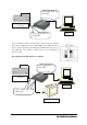
Video signal flows via BNC cable. Digital Video Recorder PC Video signal flows via LAN cable 2. If you monitor real time video through a CCTV monitor as well as a PC, connect a digital recorder to ‘Video Input’ and a CCTV monitor to ‘Video Output.’ And place the left-hand side DIP switch at lower position ‘OFF’ (the side of ‘HI-Z’). CCTV monitor is set as termination of the video signal. The right-hand side DIP swith is not available.
III. DX-VS1UE Initial Configuration 1. Installation Summary • • • • Connect ethernet cable and supply power to DX-VS1UE on local network for configuration. Install a setup program of DX-VS1UE in a PC on local network. Assign an IP address to DX-VS1UE and set administrator condition. Set user condition. 2. Connecting • Connect ethernet cable to the ethernet port on the rear. • Connect power supply unit to a power supply port on the rear.. • Confirm that the LEDs of ethernet port keep blinking.
Illustration of the method of connection When you connect a cable to the terminal, fix the screw on the upper part of the terminal completely, after loosening the screw and inserting the cable. please be careful not to shortcircuit adjacent cables. Also, please don’t twist each cable when wiring.
When you connect a cable to the terminal, fix the screw on the upper part of the terminal completely, after loosening the screw and inserting the cable. please be careful not to shortcircuit adjacent cables. Also, please don’t twist each cable when wiring.
・The circuit diagram of a sensor terminal.
3. Installing DX-VS1UE Setup Program • Copy DX-VS1Setup.exe file from the enclosed CD-ROM • Click the file on your PC to run Setup program. 4. Assigning IP Address and setting Administrator Condition * Important * To access DX-VS1UE, you firstly have to assign an appropriate IP address. When you assign an IP address to DX-VS1UE, make sure to use unoccupied IP address. For details, please ask your network administrator. ・Starting the Setup Program for DX-VS1UE Run the “DX-VS1Setup.exe”.
To change the IP address, enter the Administrator’s password and press “Change IP Addr.”, enter the new IP address and press “OK.” Button. The “Reboot” button will reboot the DX-VS1UE. This process takes 10-20 seconds. ・Setting Administrator Conditions To access the Server Configuration Page in DX-VS1UE from the Setup Menu, enter the admin’s password and press the “Start Configuration” button.
5. Connecting a digital recorder to DX-VS1UE 1) Connecting BNC cable Connect one end of BNC cable with the video input connector of DX-VS1UE and the other end with one of video output connector on the rear surface of digital recorder. Use 75ohm(3C-2V type or more) type cable as BNC cable. 2) Connecting RS-232C cable Connect RS-232C connector of a digital recorder to the RS-232(1) (refer to the following image) connector of DX-VS1UE using the attached serial cable for digital recorder connection.
Connect to RX1,TX1, GND of PTZ/DVR/CO M terminal Connect to RS232C connector on the rear surface Supplied cable serial 17 DX-VS1UE User’ User’ s Manual
IV. Accessing DX-VS1UE Homepage & Monitoring Real- time Image After assigning IP address and gateway address, subnet mask, broadcast address to DX-VS1UE properly, you may access DX-VS1UE and monitor real-time image on Internet. 1. Starting Web browser Start your web browser and enter IP address assigned to DX-VS1UE. Then you can see the user login page of DX-VS1UE. • Ex) http://192.168.1.100/ DX-VS1UE supports up to 100 simultaneous access.
DVR/PTZ level login page DVR/PTZ control page (refer to 5.
6) Application Configuration This page is used to set e-mail and file transmission function. (1) Recipient E-mail Address This is used to designate a person to receive E-mail. (2) Sender’s E-mail Address This is used to put a person’s e-mail address that is considered as the e-mail sender. This menu plays an important role since this is used for avoiding the problem that e-mails are blocked by some mail servers.
mail is sent when the sensor1 detects events. (To use sensor input detection, a sensor should be connected to DX-VS1UE. If administrator clicks on periodic sending, e-mail is sent periodically every preset time. The interval may be modified.) File name: Regarding the file name of images sent in MD or Sensor event, the file name is decided combining all options. Regarding the file name image sent in periodic sending event, administrator can decide how to name image files among three methods.
(6) FTP event configuration Administrator can set transmission conditions, image resolution, and file name. The setting method of image resolution, filename, and transmission conditions of FTP is the same as that of e-mail. Transmission Performance of E-mail and FTP ! DX-VS1UE can send e-mail once per five minutes at most in case administrator set DX-VS1UE to send e-mail periodically. If there were no restriction in sending e-mail, DX-VS1UE might cause a serious problem to the recipient’s mail server.
(3) Advanced Pan/tilt/zoom Configuration You can register preset points and set mode. When you register preset, you should stop other users from controlling pan/ tilt/zoom mechanism. For controlling Pan/tilt/zoom mechanism, please refer to Chapter IV “Accessing DX-VS1UE Homepage & Monitoring Real-time Image.” New Preset You register a new preset point as follows. You can register up to 64 presets. ! Focus on a certain point to register as a preset point controlling Pan/tilt/zoom mechanism.
set points appear. At the bottom of this window, you can check if the selected number is occupied or not. Mode Configuration There are three modes: “Normal Mode”, “Swing Mode” and “Group Mode.” ! In the normal mode, user can control pan/tilt/ zoom mechanism of an external camera through the dvr/ptz control page. ! If the swing mode is selected, the connected pan/tilt/zoom camera swings between two preset points. Time duration of “Wait (some) seconds” signifies the same meaning that of group mode.
8) Serial Port Configuration This page is used to select a communication protocol among listed ones. (1) Serial Port Selection Administrator selects a serial port to set. DX-VS1UE has three serial ports. Serial#1 and Serial#2 are RS232-C interface ports, and Serial#3 is a RS422/RS485 interface port. (2) Select Attached Device Administrator selects a communication protocol that an attached external device satisfies among listed protocols.
PTZ Command for Manual Script 1. Escape Characters # Special command @ Hexadecimal character % ^ Decimal character Character , ; Break character End of current packet & Special operation 2.
9) Sensir Input Configuration This page is used to set sensor input status. This is related with E-mail and FTP function and Alarm preset function. (1) Device Type for Input Ports Administrator defines active state of 4 digital input ports. If you connect normal open type device to input port, you should select “NO (Normal Open).” With normal close type device, you should select “NC (Normal Close).
cording to preset conditions on the “Application Configuration” page and “Alarm Configuration” page. If event keeps arising, DX-VS1UE sends images without duplicating regardless of overlapped time setting. The resolution of the image is fixed as 360x243. ※Depending on the load condition of network or server, there is the possibility that fewer pictures are transmitted than usual. (3) Alarm Preset This is used to match any preset point to one of external sensor.
(3) Login Page Editing The login pages are designed so that administrator can edit easily. Editable parts are as bellows. ! Main Title: This is used to change the title written on each login page. ! Logo Image Source URL: To show a logo image, administrator set the path or the URL where the logo image is stored. The logo appears on each login page. Please make the logo image with a height of 192 pixels or less and a width of 256pixels or less.
(appendix 1) Detailed Specifications of DX-VS1UE 1. Hardware General Power Consumption External Power Operation temperature Operation humidity Dimension Weight CPU Flash memory Main Memory OS DC 12V, 1.0A AC 24V 50/60Hz, 0.5A AC 100~250V 50/60Hz, 0.5A DC 12V, MAX: 1.5A 5℃~40℃ max 80% 121(width)×33(height)×130(depth)mm 350g 32bit RISC Embedded Processor 8M bytes 16M bytes Embedded Linux 2.
4. Misc functions and I/O Pan/tilt/zoom Control Digital recorder Control 1ch RS-232C, 1ch RS-422/RS-485 Sensor input Alarm 4 inputs support, DC4.5~13.2V 1.
(appendix 2) Serial connection with digital recorder When you connect this equipment with Mitsubishi digital recorder using serial connection, use the supplied serial cable. If you can’t use the supplied serial cable due to installation location, connect in accordance with the setting illustrated below.
(付録 3) Frequently Asked Questions 1. The feature of DX-VS1UE Q. What is the DX-VS1UE A. Video server box DX-VS1UE offers the solution of the network type remote surveillance server having many features, such as an internet server, and a picture compression device, serial device control. Monitoring and operation of the image of a digital recorder or a Pan/tilt/zoom camera can be performed through DX-VS1UE.
A. DX-VS1UE has Pan/tilt/zoom setting functions in its software. If a camera with pan/tilt/zoom functions is connected to DX-VS1UE, direction of camera lenz can be changed and zoom in/out can be executed remotely by setting in the homepage of DXVS1UE. A pan/tilt/zoom camera is connectable with RS232C, RS422, and RS485 communication interface. A. Is there any limitation on the password setting? Q. Yes.
state may happen. Q. When a fire wall is in a network, can you install DX-VS1UE and can operate it? A. In order for DX-VS1UE to transmit data and a picture, the default port number of 80th and 8080th needs to be vacant. However, usually only the 80th port is vacant in the network with a fire wall because of security. In this case, a user can change a picture transmission port into the other port which can pass fire walls from 8080th. A user can set up on Customizing Page of Server Configuration Page. Q.
is available. Q. What kind of digital recorder can be connected with DX-VS1UE? A. There is a function with which you can control a digital recorder on-line through DXVS1UE. DX-VS1UE is connected with a digital recorder via RS232-C. Mitsubishi DXTL800E can be used as a digital recorder which you can operate through DX-VS1UE. Q. There seemes to be some problem when accessing DX-VS1UE. At one time I can access the DX-VS1UE, but at other time, I cannot access the DX-VS1UE. How can I solve the problem? A.
the subnet as both your PC and DX-VS1UE is included in. Q. Regarding the setup program, If one of DX-VS1UE is chosen from the list box and the Reboot button or Start Configuration button is clicked, the setup program returns a message like “No response.” A. If the IP address of the DX-VS1UE you selected is not included in the subnet to which your PC belongs, the setup program returns a message like “No response”.