
Installation manual


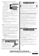

2-3-2. Mounting using "Clipping method"
"Clipping method" is the way to fix modules on the steady base
profiles (rail structure etc.,) with the "clipping" materials to catch
the top of the frame, not to directly fix with bolts and nuts on the
backside of module.
Mitsubishi Electric Corp
doesn't specify or
warrant any materials,
e.g. base profile and
clipping materials etc.,
related to clipping
method.
• Base profile should be placed in perpendicular to the longer
frame of module in principle (see figure).
•
Module shall be fixed at 4 places or more on frames.
•
Refer to the figure for the required area to be fixed.
• Close the gap between the material and frame, and secure
without loosing by M6 (1/4”) or larger bolts (M8 (5/16”)) for
where the heavy snow load is expected.
• The hooked area should be more than 5mm at least.
• Use the clipping material with sufficient strength and the
shape that can withstand forces from wind pressure and
snowfall pressure specific to local climate.
• Secure bolts with the appropriate torque avoid deformation
of the module frame.
• Take pre-caution utilizing locking fasteners to avoid
movement of the module from its original anchored position.
• Note that the drainage hole at each corner of module would
not be blocked by the base profile if the profile were placed
in parallel to the longer frame.
En-2
En-3
2-3. MOUNTING
• Use mounting framework that can withstand forces from wind
pressure and snowfall pressure specific to your local climate.
• Use mounting framework and brackets that can withstand the
environment where the PV modules are to be used. Select
proper corrosion resistant materials and coatings.
• Use appropriate safeguards and components to install the
modules.
• PV modules shall be mounted over a fire resistant roof
covering rated for the application and on any slope less than
5in/ft (127mm/305mm) to maintain a fire Class rating.
• Make sure there is enough space for air circulation behind
the PV modules to dissipate heat. Minimum 89mm (3.5
inches) standoff height must be provided.
• DO NOT open any additional holes in the modules.
• The module is Class C fire rated.
2-3-1. Mounting using bolt holes
Examples of mounting method:
• Use the 4 corner holes of the PV module to bolt with M8
(5/16”) stainless steel to the mounting framework by 4.5 to
6N·m (3.3 to 4.4 ft-lb).
•
Use spring washers and flat
washers to fasten the PV module.
• Install the PV module securely
such as fastening the
appropriate bolts with double
nuts and locking washers.
• Space more than 5 mm
between 2 modules (to
prevent from buckling a frame
of module affected by thermal
expansion).
CAUTION
WARNING
2.INSTALLATION
Refer to Local Code (US: National Electrical Code) standards
(Germany: DIN standards), construction rules and safety
instructions for installation of the PV module.
The electrical installation in Canada shall be in accordance with
CSA. C22. 1, Safety Standard for Electrical Installations,
Canadian Electrical Code, Part1.
2-1. CLIMATE CONDITIONS
Install the PV module within the following conditions:
• Ambient temperature: -20°C to 40°C (-4 to 104°F)
• Operating temperature: -20°C to 83°C (-4 to 181°F)
• Allowable pressure: below 3600Pa
• Water resistance/damage: PV modules shall not be
immersed in water and shall not be continually exposed to
water from a sprinkler, fountain, etc.
• Corrosion warning: PV module shall not be installed in
corrosive area like,
-- Salty area: area where salty water such as ocean
spray comes in direct contact with the module, or
-- Sulfurous area: area near sulfurous volcano and
sulfurous spring.
Note
In case of installation in Asian countries, PV module also
shall not be installed in corrosive area where within 500m
from a body of salt water and/or area where salty wind hit
directly.
2-2. ORIENTATION
• Install the PV modules facing South (in North Hemisphere),
or to the North (in South Hemisphere).
• PV modules connected in series should be installed at the
same orientation and angle. Different orientation or angles
may cause loss of output power due to the different
amount of sunlight exposed to each of the modules.
• Do not allow the modules to be shaded at anytime.
Shade causes loss of electrical output, even though the
factory fitted bypass diode of the PV module will reduce
such loss to some extent.
1-2. MULTIPLYING FACTOR
Under normal conditions, the PV module is likely to experience conditions that produce more current and/or voltage than reported
under Standard Test Conditions. Accordingly, the values of Isc and Voc marked on this module should be multiplied by a factor of
1.25 when determining component voltage ratings, conductor capacities (cross sectional area), fuse sizes, and size of controls
connected to the PV output. Customers in US should refer to Section 690-8 of the National Electrical Code for an additional
multiplying factor of 125 percent (80 percent derating), which may be applicable. Customers in other location should refer to the codes
relevant to the location of installation for further guidance. Voc should be increased by a factor based on the lowest ambient
temperature recorded for the location. To determine the corrected value for Maximum System Voltage follow the guidelines in article
690.7 of the NEC or applicable section in the CEC. The voltage temperature coefficient for the module in use, should be used when
determining Maximum System Voltage.
1-1. STRUCTURE
CAUTION
5mm min.
Frame (longer side)
bolt
Clipping material
Framework (base profile)
Module
(in principle)
Fig. 1 Mounting of module
Fig. 5 Grounding method #3
2-4-1. Method #1 (use of self-tapping screw)
• Secure the stainless steel screw (M5 or No.10) with 32
threads per inch to the grounding hole by 2.3N·m (20lbf-in).
• Ensure that 2 threads are engaged in the module frame.
• As shown in the figure 3, copper wire should be
compressed by the screw head.
• Stainless steel washer with appropriate corrosion resistant
coating should be inserted between copper wire and
screwhead.
• Proper cupped washer should be inserted between copper
wire and frame to avoid galvanic corrosion.
• Copper wire must have the thickness of #14 AWG or thicker,
and be secured with the module frame.
Fig. 3 Grounding method #1
2-4-2. Method #2 (use of ground lug)
• The appropriate device such as UL Listed ILSCO ground
lug, Cat. No. GBL4-DBT should be secured by stainless
steel screw (M5 or No.10) with 32 threads per inch by
2.3N·m (20lbf-in) as shown in the figure 4.
• The star or toothed washer shall be inserted between
ground lug and module frame.
• Copper wire must have the thickness of #14 AWG or thicker,
and be secured with the screw of ground lug.
Fig. 4 Grounding method #2
2-4-3. Method #3 (use of bolt and nut)
• Stainless steel bolt and nut of No.8 with 32 threads per
inchcan be used instead of No.10 self-tapping screw in
Method #2 under the following conditions.
- Torque to secure bolt: 1.8N·m (16lb-in)
- Lock or spring washer shall be inserted between nut
and toothed washer.
Fig. 2 Clipping method
Required mounting area to be fixed
2-4. GROUNDING
• The grounding method should satisfy the Local Code and
the NEC or CEC accordingly.
• Securely ground the PV modules and the mounting
framework.
Examples of proper grounding technique:
WARNING
2 Nuts
(Stainless steel, 5/16(M8))
Spring washer
(Stainless steel, 5/16)
Flat Washer
(Stainless steel, 5/16)
Mounting structure
(Alminium)
Flat Washer
(Stainless steel, 5/16)
Bolt
(Stainless steel, 5/16(M8))
Stainless steel washer
(#10)
Self-tapping screw
(Stainless steel, #10-32TPI)
Cupped washer
Copper wire (14AWG or thicker)
Module frame
(Stainless steel)
Copper wire
(14AWG or thicker)
(Stainless steel)
Stainless steel washer(#10)
Cupped washer
Module frame
Self-tapping screw
(Stainless steel, #10-32TPI)
Self-tapping screw
(Stainless steel, #10-32TPI)
Copper wire
(14AWG or thicker)
Toothed washer
(Stainless steel, #10)
Grounding lug
(ex. ILSCO GBL4-DBT)
Copper wire
(14AWG or thicker)
Grounding lug
(ex. ILSCO GBL4-DBT)
Self-tapping screw
(Stainless steel, #10-32TPI)
Toothed washer
(Stainless steel, #10)
Bolt
(Stainless steel, #8)
Nut (Stainless steel, #8)
Grounding lug
(ex. ILSCO GBL4-DBT)
Spring washer
(Stainless steel, #8)
Copper wire
(14AWG or thicker)
Toothed washer
(Stainless steel, #8)
Mounting area (4 places)
Framework (base profile)
up to 3600Pa
up to 3000Pa
up to 2400Pa
1625 (64.0)
619 (24.4)
1019 (40.1)
600 (23.6)
900 (35.4)
1200 (47.2)
1400 (55.1)
φ9[φ0.35]
21.5[0.85]
30[1.18]
46[1.81]
φ4.09
[φ0.16]
6[0.24]
E(1:2,4 PLACES)
D(1:2,4 PLACES)
φ4.09
[φ0.16]
Grounding Mark
25.3[1.00]
6[0.24]10[0.39]
10[0.39]
Drainage holes
Grounding Mark
25.3[1.00]
C(1:2,4 PLACES)
46[1.81]
1019[40.1]
1625[64.0]
1167[45.9]
φ4.09[φ0.16](4 PLACES)
1000[39.4]
φ4.09[φ0.16](4 PLACES)
1200[47.2]
A
A
B
B
C
B123456
V
W
A
A
A
W
V
V
A
(−)
(+)
A−A(1:2)
B−B(1:2)
24.5[0.96]
φ9[φ0.35](4 PLACES)
E
D