Service Handbook PUHY-80TMU-A, 100TMU-A Service Handbook PUHY-80TMU-A, 100TMU-A HEAD OFFICE MITSUBISHI DENKI BLDG. MARUNOUCHI TOKYO 100-0005 TELEX J24532 CABLE MELCO TOKYO Issued in March 2004 MEE03K198 Printed in Japan New publication effective March 2004. Specifications subject to change without notice.
Safety precautions Before installation and electric work • s Before installing the unit, make sure you read all the “Safety precautions”. s The “Safety precautions” provide very important points regarding safety. Make sure you follow them. s This equipment may have an adverse effect on equipment on the same electrical supply system. s Please report to or take consent by the supply authority before connection to the system.
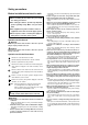
Contents 1 COMPONENT OF EQUIPMENT ............................................... 1 [1] Appearance of Components ............................................ 1 [2] Refirigerant iger Circuit Diagram and Thermal Sensor........... 6 [3] PUHY-80, 100TMU-A ELECTRICAL WIRING DIAGRAM ....................................................................... 7 [4] Standard operation data .................................................. 9 [5] Function of dip SW and rotary SW ................................
Propeller fan Fan motor -1-
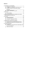
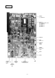
Rear Controller Box INV board MAIN board Choke coil(L2) Interrigent Power Module(IPM) Magnetic contactor(52C) Capacitor (C1)(Smoothing capacitor) Gate Amplifier board(G/A board) Diode stack(DS) Power board Terminal block(TB7)Transmission Terminal block (TB1) Power source Terminal block (TB3) Transmission -2-
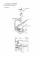
MAIN board CNS1 M-NET Transmission (DC30V) CNS2 M-NET Transmission (Centralized control) (DC30V) CN40 M-NET Transmission Power supply CNVCC3 Power source for contorl 1-2 DC30 V 1-3 DC30 V 4-6 DC12 V 5-6 DC5 V CN51 Indication distance 3-4 Compressor ON/ Off 3-4 trouble LD1 Service LED CNRS53 Serial transmission to INV board CN3D SW1,2,3,4 Dip Switch CN3S CNFAN1 control for MF1 CN20 power source CNAC3 -3-
INV board CNDC2 1-3 DC310 V CN15V2 Power supply IPM control 1-2 DC15 V 5-6 DC15 V 9-0 DC15 V C-D DC15 V CNVCC4 CNL2 Choke coil CNVCC2 power supply CNDR2 IPM control signal CNCT CNTH CNAC2 CN52C Power source Control for 1 L2 52C 5N CNFAN Control for MF1 CNRS2 Serial transmission to MAIN board -4- SW1
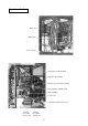
G/A board CNDC1 1 - 3 DC310V DC310V CN15V1 Power Supply IPM control 1 - 2 DC15V 5 - 6 DC15V 9 - 0 DC15V C - D DC15V CNDR1 IPM control signal Power board -5-
TH6 HEXB TH5 HEXF -6- TH8 SCC 63H CV1 ST6 Comp TH1 O/S LEV1 SV2 SV1 CP1 63HS CJ1 ST7 TH7 MA SLEV Accumulator SA High pressure safety valve CJ2 ST2 CP2 TH2 ST1 BV2 Indoor Unit BV1 [2] Refirigerant Circuit Diagram and Thermal Sensor 1 PUHY-80TMU-A, 100TMU-A
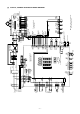
-7- 63H MF SV 2 21 S4 SV1 CH1 L3 L2 DSA CN20 (7P) White Red Black 3 5 F2 6.
-8- Name Crankcase heater (Compressor) CH1 DC reactor (Power factor improvement) Current Sensor DCL DCCT TH1 TH2 TH5 Capacitor Smoothing Magnetic contactor (Inverter main circuit) Motor Compressor ZNR1~4 C1 52C MC LEV1 L2 pipe temp.detect SLE V 63HS THHS TH8 TH7 saturation evapo.temp.detect Thermistor discharge pipe temp.
[4] Standard operation data 1 Cooling operation Outdoor units Items PUHY-80TMU-A 26.7°C(80°F)/19.4°C(67°F) Indoor Ambient temp. PUHY-100TMU-A DB/WB 35°C(95°F) Outdoor Quantity 4 4 4 4 Set Condition Indoor unit Quantity in operation – Model 24 24 Branch pipe m (Ft) 16 24 Hi Hi kg(oz) 10 5(16.4) 25(82) – Refrigerant volume 48 5(16.4) 5(16.4) 5(16.4) 5(16.4) 5(16.4) 5(16.4) Total piping length Indoor unit fan notch 10 5(16.4) Main pipe Piping 20 5(16.4) 5(16.
2 Heating operation Outdoor units Items PUHY-200TM-A 21.1°C(70°F) Indoor Ambient temp. PUHY-250TM-A DB/WB 8.3°C(47°F)/6.1°C(43°F) Outdoor Quantity 4 4 4 4 Set Quantity in operation Condition Indoor unit – Model 24 24 Branch pipe m – Refrigerant volume kg Pressure LEV opening Hi Hi Hi Hi Hi Hi Hi 12.5(441) 208 230 V/Hz 149/85 149/85 174/100 174/100 A 27.5 24.9 35.6 32.2 510 450 300 350 380 510 0 0 87 111 1.72/0.36 (249/52) 1.72/0.
[5] Function of dip SW and rotary SW (1) Outdoor unit Switch SWU SW1 SW2 Function 1~2 1~8 Unit Address Setting For self diagnosis/ operation monitoring 9~10 – 1 Centralized Control Switch 2 Deletion of connection information. SW3 – Centralized control not connected. Storing of refrigeration system connection information. – – Centralized control connected. Deletion of refrigeration system connection information. Deletion 3 Deletion of error history.
2.
(2) Indoor unit DIP SW1, 3 Switch SW1 Switch set timing OFF ON Indoor unit inlet Built in remote controller None Provided 1 Room temp. sensor position 2 Clogged filter detect. 3 Filter duration 4 OA intake 5 Remote display select. Fan output display Thermo. ON signal display 6 Humidifier control At stationary heating Always at heat. 7 Heating thermo. OFF airflow Very low speed Low speed 8 Heating thermo.
Setting of DIP SW4 Model Setting of DIP SW5 Circuit board used SW4 1 2 3 4 PDFY-10 ~ 32 ON OFF ON OFF PLFY-12 ~ 24 OFF OFF OFF ON PLFY-32 ~ 48 Phase control ON OFF OFF ON PKFY-P-8 OFF OFF ON ON PKFY-P-12 – – – – OFF OFF ON – PDFY-40, 48 Relay selection ✻ ✻ ✻ - 14 -
2 TEST RUN [1] Before Test Run (1) Check points before test run 1 Neither refrigerant leak nor loose power source/ transmission lines should be found, if found correct immediately. 2 Confirm that the resistance between the power source terminal block and the ground exceeds 2MΩ by measuring it with a DC500V megger. Do not run if it is lower than 2MΩ. Note : Never apply the megger to the MAIN board. If applied, the MAIN board will be broken.
(3) Check points for test run when mounting options Built-in optional parts Mounting of drain water pump mechanism Check point Content of test run 1 Release connector of pump circuit, check error detection by pouring water into drain pan water inlet. Result Local remote controller displays code No. “2503”, and the mechanism stops. No overflow from drain pan. Mounting of permeable film humidifier Drain water comes out by operation of drain pump. 2 After that, connect connector of circuit.
(5) Check points for system structure Check points from installation work to test run. Classification Installation and piping Power source wiring Portion Check item Trouble 1 Instruction for selecting combination of outdoor unit, and indoor unit followed? (Maximum number of indoor Not operate. units which can be connected, connecting model name, and total capacity.) 2 Follow limitation of refrigerant piping length? For example, 70m (229ft) or less (total length : 220m (721ft)) at the farthest.
DRY COOL AUTO FAN HEAT CENTRALLY CONTROLLED DAILY TIMER AUTO AUTO CLOCK ON OFF CHECK SET TEMP. REMAINDER 2 3 MODE EROR CODE TIMER CLOCK ON OFF Classification Portion Transmission line 1 System set Before starting TEST RUN ON/OFF FAN SPEED CENTRALLY CONTROLLED DAILY TIMER AUTO AUTO CLOCK ON OFF CHECK SET TEMP. REMAINDER EROR CODE MODE TIMER CLOCK ON OFF VENTILATION CHECK TEST TIMER SET ON/OFF FAN SPEED LOUVER PAR-F27MEA-US Check item FILTER TEST RUN NOT AVAILABLE SET TEMP.
[2] Test Run Method Operation procedure 1 Turn on universal power supply at least 12 hours before starting → Displaying “HO” on display panel for about two minutes 2 Press TEST button twice → Displaying “TEST RUN’’ on display panel 3 Press MODE button → Make sure that air is blowing out 4 Press MODE button to change from cooling to heating operation, and vice versa air is blowing out 5 Press FAN SPEED adjust button → Make sure that air blow is changed 6 Press AIR DIRECTION or LOUVER button to ch
3 GROUPING REGISTRATION OF INDOOR UNITS WITH M-NET REMOTE CONTROLLER (1) Switch function • The switch operation to register with the remote controller is shown below: i ii CENTRALLY CONTROLLED DAILY TIMER AUTO AUTO DRY COOL AUTO FAN HEAT CLOCK ON CHECK SET TEMP. REMAINDER FILTER VENTILATION STAND BY DEFROST C Switch to assign indoor unit address SENSOR INSIDE FAN SPEED OFF EROR CODE NOT AVAILABLE SET TEMP.
(2) Attribute display of unit • At the group registration and the confirmation/deletion of registration/connection information, the type (attribute) of the unit is displayed with two English characters. Display Type (Attribute) of unit/controller Indoor unit connectable to remote controller Outdoor unit Local remote controller System controller (MJ) [Description of registration/deletion/retrieval] • The items of operation to be performed by the remote controller are given below.
(3) Group registration of indoor unit 1) Registration method • Group registration of indoor unit ........................................................................ 1 The indoor unit to be controlled by a remote controller is registered on the remote controller. [Registration procedure] 1 With the remote controller under stopping or at the display of “HO”, continuously press the FILTER + LOUVER button ( A + B ) at the same time for 2 seconds to change to the registration mode. (See the figure below.
2) Method of retrieval/confirmation • Retrieval/confirmation of group registration information on indoor unit ............... 2 The address of the indoor unit being registered on the remote controller is displayed. [Operation procedure] 1 With the remote controller under stopping or at the display of “HO”, continuously press the FILTER + LOUVER button ( A + B) at the same time for 2 seconds to change to the registration mode.
• Registered ßC (Alternative display) ßC SET TEMP. MODE ON/OFF CLOCK ON OFF TIMER FAN SPEED LOUVER AIR DIRECTION FILTER VENTILATION CHECK TEST TIMER SET PAR-F27MEA-US 2 ßC 1+ 2 (Alternative display) 2 Press the switch for confirmation ( E) 1 Set the address ßC ˚C INDOOR UNIT ADDRESS NO ERROR CODE OA UNIT ADDRESS NO * • No registration Same display will appear when the unit of “007” is not existing.
4) Deletion of information on address not existing • Deletion of information on address not existing ................................................... 5 This operation is to be conducted when “6607” error (No ACK error) is displayed on the remote controller caused by the miss setting at test run, or due to the old memory remained at the alteration/modification of group composition, and the address not existing will be deleted.
4 CONTROL [1] Control of Outdoor Unit (1) Initial processing • When turning on power source, initial processing of microcomputer is given top priority. • During initial processing, control processing corresponding to operation signal is suspended. The control processing is resumed after initial processing is completed. (Initial processing : Data processing in microcomputer and initial setting of each LEV opening, requiring approx. 2 minutes at the maximum.
(4) Frequency control • Depending on capacity required, capacity control change and frequency change are performed to keep constant evaporation temperature (0˚C) in cooling operations, and high pressure (18kg/cm2G) in heating operation. • Frequency change is perfprmed at the rate of 3Hz/second across 20 ~ 110Hz range. 1) Frequency control starting • 60Hz is the upper limit for 3 minutes after starting.
3 Back up of frequency control by bypass valve During 20Hz operations, frequency is backed up by turning on (opening) bypass valve (SV2). • Cooling During 20Hz operations 3 minutes after starting compressor, bypass valve is ON turned on when ET is -30˚C (-22°F) or less, and turned off when ET is -15˚C (5°F) or more. OFF • Heating -30˚C -15˚C During 20Hz operations 3 minutes after starting compressor, SV2 turned on (-22°F) (5°F) when high pressure (Pd) exceeds pressure limit (See previous page.
5) Change in number of operating indoor units during defrosting operations • In case number of operating indoor units changes during defrosting operations, the defrosting operations continue, and control of unit number change is performed after the defrosting operations are finished. • Even in case all indoor units stop or thermostat is turned off during defrosting operations, the defrosting operations do not stop until expected defrosting activities are completed.
(10) Refrigerant recovery control Refrigerant recovery is conducted to prevent refrigerant from accumulating in the stopped unit (fan unit), the unit under cooling mode and that with heating thermostat being turned off. 1) Start of refrigerant recovery 1 Refrigerant recovery is started when the two items below are fully satisfied. • 30 minutes has passed after finishing refrigerant recovery. • The level detector detects AL = 0 for 3 minutes continuously, or when the discharge SH is high.
[2] Operation Flow Chart (1) Outdoor unit (Cooling, heating modes) Start NO Normal operations Trouble observed Stop Breaker turned on YES "HO" blinks on remote controller temperature display Note: 1 NO Set indoor address No. to remote controller YES 2 NO Operation command 1. Protection function selfholding cancelled 2. Oil return LEV, SC coil LEV fully closed YES Fan Operation mode Cooling, Heating 1. 2. 3. 4.
(2) Indoor unit (Cooling, heating, dry, and fan modes) Start Normal operations Breaker turned on Trouble observed NO Stop YES 1 Operation SW turned on YES NO 1. Protection function self-holding cancelled 2. Indoor unit LEV fully closed Remote controller display extinguished Note: 2 Error mode NO YES Operation mode YES 1. Aux. heater OFF 2. 1 minute low FAN speed Aux.
(3) Cooling operation Cooling operation Normal operations 4-way valve OFF Test run Stop Indoor unit fan operations Test run start Note: 1 YES NO NO Thermostat ON YES YES 3-minute restart prevention NO 1. Inverter output 0Hz 2. Indoor unit LEV, oil return LEV, Subcool coil bypass LEV fully closed 3. Solenoid valve OFF 4. Outdoor unit fan stop 1. Inverter frequency control 2. Indoor unit LEV, oil return LEV, Subcool coil bypass LEV fully closed 3. Solenoid valve control 4.
(4) Heating operation (Only for PUHY) Normal operations Defrosting operations Stop Test run Heating operation Note: 1 Note: 2 Defrosting operation YES 4-way valve OFF 4-way valve ON Test run start YES NO NO Thermostat ON YES YES 1. Indoor unit fan stop 2. Inverter defrost frequency control 3. Indoor unit LEV fully opened, oil return LEV fully closed, Subcool bypass LEV fully opened 4. Solenoid valve control 5.
(5) Dry operation Dry operations Normal operations Thermostat ON 4-way valve OFF Stop Test run start YES Note: 2 Thermostat ON NO NO > 18˚C Inlet temp.= YES Note: 1 1. Indoor unit fan stop 2. Inverter output 0Hz 3. Indoor unit LEV, oil return LEV, Subcool bypass LEV fully closed 4. Solenoid valve OFF 1. Outdoor unit (Compressor) intermittent operations 2. Indoor unit fan intermittent YES operations (Synchronized with compressor : low speed, OFF operations) 5.
[3] List of Major Component Functions Name Symbol (function) Part code Application Compressor MC Adjust refrigerant circulation by controlling operating frequency and capacity control valve with operating pressure. Pressure sensor 63HS 1) High press. detection.
Name Solenoid valve Symbol (function) Application Specification SV1 (discharge suction bypass) 1) High/low press. bypass at starting/ AC 220V stopping and capacity control at Open at energizing and close at deenergizing low load 2) Discharge press. rise suppression SV2 (discharge suction bypass) Capacity control and high press.
[4] Resistance of Temperature Sensor Thermistor for low temperature Thermistor Ro= 15kΩ ± 3% (TH5 ~ 8) 1 1 )} Rt = 15exp {3460 ( 273+tc 273+0 9 ∗˚F= × ˚C + 32 Thermistor R120 = 7.465kΩ ± 2% (TH1) 1 1 Rt = 7.
5 REFRIGERANT AMOUNT ADJUSTMENT Clarify relationship between the refrigerant amount and operating characteristics of CITY MULTI, and perform service activities such as decision and adjustment of refrigerant amount on the market. [1] Refrigerant Amount and Operating Characteristics The followings are refrigerant amount and operating characteristics which draw special attention.
(2) Refrigerant Volume Adjustment Operation 1) Operating Characteristics Refrigerant Volume Characteristic items related to operating characteristics and the refrigerant volume are shown below. 1 If the number of indoor units in operation increases during cooling, the required volume of refrigerant tends to increase (the amount of refrigerant in the accumulator tends to decrease), but the change is minimal.
b Check the refrigerant volume by self-diagnosis using the LED. Set the self-diagnosis switch (SW1) as shown below and check the past information (history) concerning the refrigerant volume. 1 2 3 4 5 6 7 8 9 10 Set SW1 as shown in he figure at right. ON If LD8 lights up, it indicates the refrigerant charge abnormal delay state just before emergency stop due to refrigerant overcharge (1500).
3) Refrigerant Volume Adjustment Mode Operation 1 Procedure Depending on the operating conditions, it may be necessary either to charge with supplementary refrigerant, or to drain out some, but if such a case arises, please follow the procedure given below flow chart. 1 Switching the function select switch (SW2-4), located on the outdoor unit's control board, ON starts refrigerant volume adjustment mode operation and the following operation occurs.
Refrigerant adjustment method Start = Yes Note 1, Operated using outdoor unit DIP SW3-1 and 3-2.
6 TROUBLESHOOTING [1] Principal Parts Pressure Sensor (1) Judging Failure 1) Check for failure by comparing the sensing pressure according to the high pressure sensor and the pressure gauge pressure. Turn on switches 1, 3, 5, 6 of the digital display select switch (SW1) as shown below, and the sensor pressure of the high pressure sensors is displayed digitally by the light emitting diode LD1.
✻Connector connection specifications on the pressure sensor body side. The connector’s pin numbers on the pressure sensor body side differ from the pin numbers on the main circuit board side. Sensor Body Side Pin 1 Pin 2 Pin 3 Vcc Vout GND MAIN Board Side Pin 3 Pin 2 Pin 1 Solenoid Valve (SV1, SV2) Check if the control board’s output signals and the operation of the solenoid valves match.
Outdoor LEV The valve opening angle changes in proportion to the number of pulses. (Connections between the outdoor unit’s MAIN board and SLEV, LEV1 (outdoor electronic expansion valve)) Gray Driver Circuits Black Yellow Red Orange Outdoor MAIN Board (Connectors CNLV1, CNLV2) Pulse Signal Output and Valve Operation Output (Phase) No.
Judgment Methods and Likely Failure Mode Caution: The specifications of the outdoor unit (outdoor LEV) and outdoor units (indoor LEV) differ. For this reason, there ar e cases where the treatment contents differ, so follow the treatment specified for the appropriate LEV as indicated in the right column. Failure Mode Microcomputer Driver Circuit Failure Judgment Method Treatment Disconnect the control board connector and connect the check LED as shown in the figure below.
Outdoor LEV (SLEV, LEV1) Coil Removal Procedure (configuration) As shown in the figure, the outdoor LEV is made in such a way that the coils and the body can be separated. Coils Body Stopper Indentation for Stopper (12 places around the circumference) Lead Wires Fasten the body tightly at the bottom (Part A in the figure) so that the body will not move, then pull out the coils toward the top.
Intelligent Power Module (IPM) Measure resistances between each terminal of IPM with tester, and use the results for troubleshooting. 1 Focus on whether there is a complete open (∞Ω) state or short-circuit (~0Ω). The measured resistance value is a guideline and may deviate slightly. Measure between several similar measurement points. If the value does not differ by more than double or half from the other points, then judge the state as OK.
(5) Trouble and remedy of remote controller Symptom 1 Cause Despite pressing of remote controller switch, operation does not start with no electronic sound. (No powering signal appears.) 2 At about 10 seconds after turning remote controller operation switch ON, the display distinguishes and the operation stops. Checking method & countermeasure 1) M-NET transmission power source is not supplied a) Check transmission terminal block of refrom outdoor unit. mote controller for voltage.
Symptom 3 Cause “HO” display on remote controller does not disappear and switch is ineffective. (Without using MELANS) 1) Outdoor unit address is set to “00.” 2) Erroneous address 1Address setting miss of indoor unit to be coupled with remote controller (Remote controller is not set to - 100.) 2Address setting miss of remote controller (Indoor unit is not set to + 100.
Symptom 4 “88” appears on remote controller at the registration and access remote controller Cause Checking method & countermeasure [Generates at registration and confirmation] 1) Erroneous address of unit to be coupled 2) Slipping off of transmission line of unit to be coupled (No connection) 3) Faulty circuit board of unit to be coupled 4) Installation miss of transmission line a) Confirm the address of unit to be coupled. b) Check the connection of transmission line.
Transmission Power Circuit (30 V) Check Procedure If “ ” is not displayed by the remote control, investigate the points of the trouble by the following procedure and correct it. No. Check Item 1 Disconnect the transmission line from TB3 and check the TB3 voltage. 2 3 4 5 6 7 Judgment Response DC24~30 V Check the transmission line for the following, and correct any defects. Broken wire, short circuit, grounding, faulty contact. Except the above-mentioned to No.
1) Investigation of transmission wave shape/noise Control is performed by exchanging signals between outdoor unit, indoor unit and remote controller by M-NET transmission. If noise should enter into the transmission line, the normal transmission will be hindered causing erroneous operation. Symptom caused by the noise entered into transmission line Cause Noise entered into transmission line Error code Signal changes and is misjudged as the signal of other address.
3) Checking and measures to be taken (a) Measures against noise Check the items below when noise can be confirmed on wave shape or the error code in the item 1) is generated. Measures to be taken 1 Wiring of transmission and power lines in crossing Isolate transmission line from power line (5cm or more). Never put them in a same conduit. 2 Wiring of transmission line with that of other system in bundle Wire transmission line isolating from other transmission line.
4) No. 1 Treatment of Inverter and Compressor Troubles If the compressor does not work when error codes 4240 or 4250 are detected, determine the point of malfunction by following the steps in the appropriate sections on the pages starting from page 75, then perform the procedures below. Check Item How many hours was the power kept on before operation? Symptoms Treatment 1 If it was kept on for 2 hours or longer as specified Go to [2]. 2 It was kept on for less than the specified period.
5) Troubleshooting at breaker tripping Check items Measures to be taken 1 Check the breaker capacity. The breaker’s capacity should be proper. 2 Check the a short circuit or grounding in the electrical system other than the inverter. Correct any defects. 3 Check the resistance between terminals on the terminal block TB1 for power source. Check each part inside the inverter power circuit (resistance, megohm or the like). a) Diode stack Refer to "Troubleshooting of diode stack.
6) Individual Parts Failure Judgment Methods. Part Name Judgment Method Diode Stack (DS) Refer to “Judging Diode Stack Failure.” (P49) Intelligent Power Module (IPM) Refer to “Judging IPM Failure.” (P49) Electromagnetic Contactor (52C) Measure the resistance value at each terminal.
Model PUHY-80TMU-A, 100TMU-A To compressor Red White Blue Blue Red board - 59 - To capacitor (C1)
Check Code List Check Code Check Content 0403 Serial transmission trouble 0900 Trial operation 1102 Discharge temperature trouble 1111 Low pressure saturation temperature sensor trouble (TH2) 1302 High pressure trouble 1500 Refrigerant volume charge trouble 1505 Suction pressure trouble 2500 Leakage (water) trouble 2502 Drain pump trouble 2503 Drain sensor trouble 4102 Lacking power source error 4103 Reverse phase error/Lacking power source error 4115 Power supply sync signal trou
Check Code Check Content 6606 Communications with transmission processor abnormality 6607 No ACK abnormality 6608 No response abnormality 6831 MA communication, No-reception error 6832 MA communication, Synchronization recovery error 6833 MA communication, Transmission/reception handware error 6834 MA communication, Start bit error 7100 Total capacity abnormality 7101 Capacity code abnormality 7102 Connected unit count over 7105 Address setting abnormality 7106 Characteristics setti
[2] Self-diagnosis and Countermeasures Depending on the Check Code Displayed (1) Mechanical Checking code 0403 Serial transmission trouble Meaning, detecting method If serial transmission cannot be established between the MAIN and INV boards Cause Checking method & Countermeasure 1) Wiring is defective. Check 1, the connections, 2, contact at the connectors and 3, for broken wires in the following wiring.
Checking code 1111 Low pressure saturation temperature sensor trouble (TH2) Meaning, detecting method 1. When saturation temperature sensor (TH2) detects –40°C or less (the first time) during operations, outdoor unit stops once, mode is changed to restart mode after 3 minutes, then the outdoor unit restarts. Cause 1) Gas leak, Gas shortage See Refrigerant amount check. 2) Insufficient load operations Check operating conditions and o p eration status of outdoor unit.
Checking code Meaning, detecting method 1302 High pressure trouble 1 (Outdoor unit) 1. When press. sensor detects 28kg/cm2 or more during operations (the first time), outdoor unit stops once, mode is changed to restart mode after 3 minutes, then the outdoor unit restarts. Cause 1) Poor operations of indoor LEV 3. When 28kg/cm 2 or more pres-sure is detected 30 or more minutes after stop of outdoor unit, the detection is regarded as the first time and the process shown in 1 is observed. 4.
Checking code Meaning, detecting method 1302 High pressure trouble 1 (Outdoor unit) Cause Checking method & Countermeasure 16)Control circuit board thermistor trouble, press. sensor input circuit trouble Check inlet temperature and press. of sensor with LED monitor. 17)Poor mounting of thermistor (TH2, TH5, H6) 18)Coming loose the connecter of pressure switch or cut of the wire. High pressure trouble 2 (Outdoor unit) 1500 Overcharged refrigerant abnormality When press.
Checking code Meaning, detecting method 2500 Leakage (water) trouble When drain sensor detects flooding during drain pump OFF. 1) Water leak due to humidifier or the Check water leaking of humidifier and clogging of drain pan. like in trouble. 2502 Drain pump trouble The drain sensor's water drain* and after the drain pump is turn on for more than three minuites. 1) Drain sensor sinks in water be- Check operations of drain pump.
Checking code 4102 Open phase error 4103 Reverse phase error Meaning, detecting method Open phase in the power system is being detected, so operation cannot be started. Reverse phase (or open phase) in the power system is being detected, so operation cannot be started. Cause Checking method & Countermeasure 1) Open phase has occurred in the Check before the breaker, after the power supply (R, S, T).
Checking code 4115 Power supply sync signal trouble 4116 Fan speed trouble (motor trouble) Meaning, detecting method The frequency cannot be determined when the power is switched on. (The power supply’s frequency cannot be detected. The outdoor fan cannot be controlled by phase control.) (Detects only for PKFY-NAM) 1. Detecting fan speed below 180rpm or over 2000rpm during fan operation at indoor unit (first detection) enters into the 3-minute restart prevention mode to stop fan for 30 seconds. 2.
Checking code 4200 VDCsensor/ circuit trouble Meaning, detecting method 150 V is detected 1 If VDC just before the inverter starts. 2 If VDC 400 V is detected just before the inverter starts. 3 If the voltage of the INV board’s sensor circuit input is what it should not normally be. Cause Checking method & Countermeasure 1) Power supply voltage is abnormal. • Check if an instantaneous power failure or power failure, etc. has occurred. • Check if the voltage is the rated voltage value.
Checking code 4220 Bus voltage trouble 4230 Radiator panel overheat protection Meaning, detecting method If VDC 220 V is detected during inverter operation. If the cooling fan stays ON for 5 minutes or longer during inverter operation, and if THHS 92 °C is detected. Cause Checking method & Countermeasure 1) The power supply voltage is abnormal. • Check if an instantaneous stop or power failure, etc. has occurred. • Check if the voltage is the rated voltage value. 2) The wiring is defective.
Checking code 4240 Overcurrent protection 4250 Breaking of overcurrent Meaning, detecting method If IDC 103 A is detected continuously for 10 minutes during operation of the inverter after 5 or more seconds have passed since the inverter started. Cause Checking method & Countermeasure 1) Air passage Short Cycle Is the unit’s exhaust short cycling? 2) The heat exchanger is clogged. Clean the heat exchanger.
Checking code 4260 Cooling fan trouble Meaning, detecting method If the heat sink temperature (THHS) 60°C for 10 minutes or longer just before the inverter starts. 5110 Radiator panel If a heat sink temperature of (THHS) 40°C is detected just before starting of, and during operation of the inverter.
Checking code 5101 5105 5106 5107 5108 Thermal Sensor Error, Outdoor Unit 5102 Meaning, detecting method Discharge 1 A short in the thermistor or (TH1) an open circuit was sensed. The outdoor unit switches to Low the temporary stop mode pressure with restarting after 3 minsaturation utes, then if the temperature (TH2) detected by the thermistor just before restarting is in the normal range, restarting takes place.
(2) Communication/system Checking code 6600 Meaning, detecting method Multiple address error Transmission from units with the same address is detected. Note: The address/attribute shown on remote controller indica tes the controller which has detected error. Cause Checking method & Countermeasure 1) Two or more controllers of outdoor unit, indoor unit, remote controller, etc. have the same address. 2) In the case that signal has changed due to noise entered into the transmission signal.
Checking code 6602 Meaning, detecting method Transmission processor hardware error Cause Checking method & Countermeasure Checking method and processing YES Transmission line installed while turning power source on? Shut off the power source of outdoor/indoor units/BC controller and make it again. NO Check power source of indoor unit.
Checking code 6606 Meaning, detecting method Communications with transmission processor error Cause Checking method & Countermeasure 1) Data is not properly transmitted due to casual errouneous operation of the generating controller. 2) Faulty generating controller. Turn off power sources of indoor unit and outdoor unit. When power sources are turned off separately, microcomputer is not reset and normal operations can not be restored.
Checking code 6607 Meaning, detecting method No ACK error When no ACK signal is detected in 6 continuous times with 30 second interval by transmission side controller, the transmission side detects error. Note: The address/attribute shown on remote controller indicates the controller not providing the answer (ACK). System compo- Generating sition unit address 1 Outdoor unit (OC) Display Detecting of trouble method Cause 1) Poor contact of transmission line of OC or IC.
Checking code Meaning, detecting method No ACK error 6607 (continued) When no ACK signal is detected in 6 continuous times with 30 second interval by transmission side controller, the transmission side detects error. Note: The address/attribute shown on remote controller indicates the controller not providing the answer (ACK).
Checking code Meaning, detecting method 6607 No ACK error (continued) When no ACK signal is detected in 6 continuous times with 30 second interval by transmission side controller, the transmission side detects error. Note: The address/attribute shown on remote controller indicates the controller not providing the answer (ACK).
Checking code Meaning, detecting method When no ACK signal is detected in 6 continuous times with 30 second interval by transmission side controller, the transmission side detects error. 6607 No ACK error (continued) Note: The address/attribute shown on remote controller indicates the controller not providing the answer (ACK).
Checking code 6608 Meaning, detecting method No response error Though acknowledgement of receipt (ACK) is received after transmission, no response command is returned. Detected as error by transmission side when the same symptom is re-peated 10 times with an interval of 3 seconds Note: The address/attribute shown on remote controller indicates the controller which has detected error.
Checking code Meaning, detecting method Cause Checking method & Countermeasure 7102 Connected unit count over 2) The Outdoor unit address is being set to 51~100 under automatic address mode (Remote controller displays “HO”). 3) Slipping off of transmission wiring at Outdoor unit. 4) Short circuit of transmission line in case of 3) & 4), remote controller displays “HO”. a) Check for the model total (capacity code total) of indoor units connected.
[3] LED Monitor Display E: E2 Contents stored in the E2PROM; M: Monitored by the IC through communications; E*: Stored in service memory. No 0 SW1 12345678910 Item LD1 0000000000 Relay Output Display 1 (Lights up to display) COMP Operating Display LD4 LD5 LD2 LD3 Crankcase Heater 21S4✻ SV1 Remarks LD6 LD7 LD8 is a relay output indicator which Lights for lights u at all times when the Normal microcomputer’s power is ON.
No SW1 12345678910 Item LD1 LD2 LD3 Display LD4 LD5 Remarks LD6 21 1010100000 Outdoor Unit Preliminary Error History High Low Outlet Overcur- Heat Sink OvercurPressure Pressure Tempera- rent Thermostat rent Error 1, 2 Error ture Error Protection Operation Break 22 0110100000 Suction Configuration Pressure Detection Error Error 23 1110100000 TH1 Error TH2 Error 24 0001100000 TH7 Error TH8 Error 25 1001100000 Error History 1 26 0101100000 Inverter Error Detail 27 1101100000 Error History 2 2
No SW1 12345678910 Item LD1 LD2 LD3 Display LD4 LD5 Remarks LD6 LD7 LD8 E✻ -99.9 ~ 999.9 52 0010110000 THHS Data 53 1010110000 HPS Data ↑ 54 0110110000 TH7 Data ↑ 55 1110110000 TH8 Data ↑ 56 0001110000 57 1001110000 58 0101110000 59 1101110000 Accumulator Level 0~9 (“AL=” is also displayed) ∆ Hz 0 ∆ Hz + ∆ AK – ∆ AK 0 ∆ AK + Stable region High 1~2 deg. High 2~3 deg. High 3 deg. or more Stable region High 1~2 deg. High 2~3 deg. High 3 deg.
When there is an error stop with No92-111, the data on error stops or the data immediately before the error postponement stop, which is stored in service memory, are displayed.
No SW1 12345678910 Item LD1 LD2 LD3 Display LD4 LD5 117 10101110 IC6 inlet temperature -99.9 ~ 999.9 118 01101110 IC7 inlet temperature ↑ 119 11101110 IC8 inlet temperature ↑ 120 00011110 IC9 inlet temperature ↑ 121 10011110 IC10 inlet temperature ↑ 122 01011110 IC11 inlet temperature ↑ 123 11011110 IC12 inlet temperature.
No SW1 12345678910 Item LD1 LD2 LD3 Display LD4 LD5 155 11011001 IC12 gas piping temp. -99.9 ~ 999.9 156 00111001 IC13 gas piping temp. ↑ 157 10111001 IC14 gas piping temp. ↑ 158 01111001 IC15 gas piping temp. ↑ 159 11111001 IC16 gas piping temp.
No SW1 12345678910 Item LD1 LD2 LD3 Display LD4 LD5 194 01000011 IC3 LEV Opening -99.9 ~ 999.
No SW1 12345678910 Item LD1 LD2 LD3 Display LD4 LD5 232 00010111 IC9 capacity code 0000 ~ 9999 233 10010111 IC10 capacity code ↑ 234 01010111 IC11 capacity code ↑ 235 11010111 IC12 capacity code ↑ 236 00110111 IC13 capacity code ↑ 237 10110111 IC14 capacity code ↑ 238 01110111 IC15 capacity code ↑ 239 11110111 IC16 capacity code ↑ 240 00001111 IC1 filter ↑ 241 10001111 IC2 filter -99.9 ~ 999.
Service Handbook PUHY-80TMU-A, 100TMU-A Service Handbook PUHY-80TMU-A, 100TMU-A Issued in March 2004 New publication effective March 2004. Specifications subject to change without notice.
3400 Lawrenceville Suwanee Road ● Suwanee, Georgia 30024 Toll Free: 800-433-4822 ● Toll Free Fax: 800-889-9904 www.mrslim.com Specifications are subject to change without notice.