
Instruction manual

PARAMETERS
163
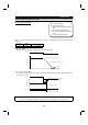
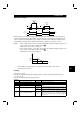
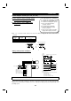
<Operation example>
CS
STF (STR)
OFF
ON
Pr.5
Pr.4
Pr.5
A
×
Pr.5
1
2
×
Pr.5
1
2
B
Terminal
Less than Pr. 271 setting rated current
Pr. 272 setting rated current or more
Power running
Regenerating
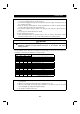
•
When operation is performed with X19 (load detection high-speed frequency function selection) signal on,
the inverter automatically varies the maximum frequency between Pr. 4 “multi-speed setting (high speed)”
and Pr. 5 "multi-speed setting (middle speed)" settings as shown below according to the average current
flowing during acceleration from the frequency half of the Pr. 5 setting to the frequency set in Pr. 5.
Example: 1. If the average current is not more than the following, the maximum running frequency is the
value set in Pr. 4 as shown in operation example
A
.
Rated inverter current
×
Pr. 271 setting (%)
2. If the average current is not less than the following, the maximum running frequency is the
value set in Pr. 5 as shown in operation example
B
.
Rated inverter current
×
Pr. 272 setting (%)
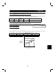
Pr.4
(120Hz)
Pr.5
(60Hz)
Pr.271
(50%)
Pr.272
(100%)
Average current
Frequency
<In this example, the frequency varies according to the current; 60Hz for 100% current
and 120Hz for 50% current.>
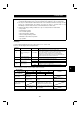
<Setting>
1) Set "2 or 3" in Pr. 270.
2) Assign X19 (load detection high-speed frequency function selection) to the input terminal using any of
Pr. 180 to Pr. 186.
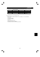
3) Refer to the following table and set the parameters:
Parameter
Number
Name Setting Description
4 Multi-speed setting (high speed) 0 to 400Hz Set the higher-speed frequency.
5 Multi-speed setting (middle speed) 0 to 400Hz Set the lower-speed frequency.
271 High-speed setting maximum current 0 to 200%
272 Mid-speed setting minimum current 0 to 200%
Set the upper and lower limits of the current at high and middle
speeds.
0 to 400Hz
(Average current during acceleration from (Pr. 273
×
1/2) Hz to
(Pr. 273) Hz can be achieved.
273 Current averaging range
9999
Average current during acceleration from (Pr. 5
×
1/2) Hz to
(Pr. 5) Hz is achieved.
274 Current averaging filter constant 1 to 4000
Set the time constant of the primary delay filter relative to the
output current.
(The time constant [ms] is 0.75
×
Pr. 274 and the factory
setting is 12ms.) A larger setting provides higher stability but
poorer response.
4