
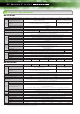
Specifications
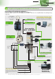
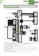
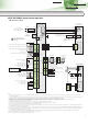
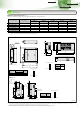


Standard Wiring Diagram
Easy Operation
High Performance
Global Standard
14
Servo amplifier
MR-E-M-AG-KH003
(Note 10)
RS-232C
TXD
GND
RXD
3
5
2
(Note 9)
15m maximum
Personal computer
running
Microsoft Windows
Maximum +1mA total
Double oscillation (±10V output)
Monitor output
Analog monitor output 1
Analog monitor output 2
10kΩ
10kΩ
2m maximum
U
V
W
1P5
2LG
3
MR
4
MRR
SD
PLATE
SM
A
U
V
W
B
C
D
B1
B2
CN2
(Note 10)
P5E
P5G
MR
MRR
SHD
Electromagnetic
brake (Note 7)
(Note 12)
Servo motor
HF-SEM(B)JW1-S100
Servo motor
HF-KEM(B)W1-S100
P
C
L1
L2
L3
U
V
W
D
Encoder
Encoder
1
P5
2
LG
3
MR
4
MRR
SD
PLATE
P5
LG
MR
MRR
SD
NFB
MC
Power supply
3-phase 200 to 230VAC
or
1-phase 230VAC (Note 11)
Optional
regeneration unit
(Note 13)
CNP 1 CNP 2
MO14
A
A
MO2
6
LG
3
SD
PLATE
RXD1
LG3
SD
PLATE
TXD2
CN3
CN2
(Note 8)
(Note 8)
(Note 8)
(Note 8)
The servo amplifier may be
damaged if the optional
regeneration unit is incorrectly
connected.
(Note 14)
Built-in
regenerative
resistor
EMG
Shut off when
the servo on
signal or the alarm
signal turns off.
24VDC
Notes:
1. Do not reverse the diode’s direction. Connecting it backwards could cause the servo amplifier to malfunction such that signals are not output, and emergency stop and other safety
circuits are inoperable.
2. Provide a 24VDC±10% 200mA power supply from an external source for the interface. 200mA is the value when all input/output signals are used. Note that the current capacity can be
stepped down according to the number of input/output points in use. Refer to “MR-E-MA/AG-KH003 INSTRUCTION MANUAL” for details.
3. Always turn on the emergency stop (EMG) signal (normally closed contact) before starting the operation. If not, the operation will not start.
4. Always turn on the forward/reverse stroke end (LSP/LSN) signals (normally closed contact) before starting the operation. If not, the commands will not be accepted.
5. Signals with the same name are connected internally.
6. The malfunction (ALM) signal (normally closed contact) is conducted to SG in normal alarm-free condition.
7. This is for the motor with an electromagnetic brake. The electromagnetic brake terminals (B1, B2) do not have polarity.
8. Connect the shield wire securely to the plate inside the connector (ground plate).
9. A shielded multicore cable must be used. The cable length up to 15m is possible in a low noise environment. However, if the RS-232C communication is set up with a baud rate of more
than 38400bps, keep the cable length within 3m.
10. The signals shown apply when using a two-wire type encoder cable. Encoder cable 30m or longer is four-wire type. Refer to “MR-E-MA/AG-KH003 INSTRUCTION MANUAL” for details.
11. When using a power supply, 1-phase 230VAC, connect the power supply to the L1 and L2 terminals. Do not connect anything to L3. The 1-phase 230VAC power supply is available only
for the MR-E-70AG-KH003 or smaller servo amplifier.
12. Use the analog monitor/RS-232C branch cable (MR-E3CBL15-P) when connecting the analog monitor output 1 (MO1), analog monitor output 2 (MO2) and a personal computer.
13. Disconnect P and D when connecting the optional regeneration unit externally.
14. Connect P and D when using the built-in regenerative resistor.
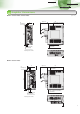
External 24VDC
power supply (0.2A or more)
R
A
1
R
A
2
R
A
3
R
A
4
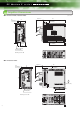
●Connection example
B1
B2
SM
Electromagnetic
brake
(Note 7)
U
V
W
Shut off when the servo on
signal or the alarm signal
turns off.
EMG
Power supply 24VDC for
the electromagnetic brake
2
3
4
1
1
2
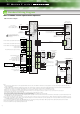
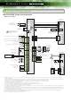
MR-E-AG-KH003: Speed control operation
Encoder Z-phase pulse (differential line driver)
Encoder A-phase pulse (differential line driver)
Encoder B-phase pulse (differential line driver)
Control common
Control common
Encoder Z-phase pulse (open collector)
LG 14
OP
21
SD
2m maximum
10m maximum
10m maximum
RD
11
LZ
19
LZR
20
LA
15
LAR
16
LB
17
LBR
18
PLATE
EMG
8
SON
4
ST1
3
ST2 5
LSP 6
LSN 7
SG 13
10m maximum
2m maximum
ZSP
12
ALM
9
VIN
1
SA
10
VC
26
LG
14
TLA
2
SD
PLATE
Servo on
Analog speed command
-10V to +10V
Analog torque limit
0V to +10V
Reverse rotation start
Emergency stop
Forward stroke end
Reverse stroke end
Forward rotation start
(Note 3)
(Note 4)
(Note 1)
Malfunction
Zero speed detection
Speed reached
(Note 6)
Ready
(Note 2)
CN1
(Note 5)