General-Purpose AC Servo MODEL MR-E- A/AG INSTRUCTION MANUAL B
Safety Instructions (Always read these instructions before using the equipment.) Do not attempt to install, operate, maintain or inspect the servo amplifier and servo motor until you have read through this Instruction Manual, Installation guide, Servo motor Instruction Manual and appended documents carefully and can use the equipment correctly. Do not use the servo amplifier and servo motor until you have a full knowledge of the equipment, safety information and instructions.
1. To prevent electric shock, note the following: WARNING Before wiring or inspection, switch power off and wait for more than 10 minutes. Then, confirm the voltage is safe with voltage tester. Otherwise, you may get an electric shock. Connect the servo amplifier and servo motor to ground. Any person who is involved in wiring and inspection should be fully competent to do the work. Do not attempt to wire the servo amplifier and servo motor until they have been installed.
. Additional instructions The following instructions should also be fully noted. Incorrect handling may cause a fault, injury, electric shock, etc. (1) Transportation and installation CAUTION Transport the products correctly according to their weights. Stacking in excess of the specified number of products is not allowed. Do not carry the servo motor by the cables, shaft or encoder. Do not hold the front cover to transport the servo amplifier. The servo amplifier may drop.
(2) Wiring CAUTION Wire the equipment correctly and securely. Otherwise, the servo motor may misoperate. Do not install a power capacitor, surge absorber or radio noise filter (FR-BIF option) between the servo motor and servo amplifier. Connect the output terminals (U, V, W) correctly. Otherwise, the servo motor will operate improperly. Do not connect AC power directly to the servo motor. Otherwise, a fault may occur.
(5) Corrective actions CAUTION When it is assumed that a hazardous condition may take place at the occur due to a power failure or a product fault, use a servo motor with electromagnetic brake or an external brake mechanism for the purpose of prevention. Configure the electromagnetic brake circuit so that it is activated not only by the servo amplifier signals but also by an external emergency stop signal (EMG).
About processing of waste When you discard servo amplifier, a battery (primary battery), and other option articles, please follow the law of each country (area). FOR MAXIMUM SAFETY This product is not designed or manufactured to be used in equipment or systems in situations that can affect or endanger human life.
COMPLIANCE WITH EC DIRECTIVES 1. WHAT ARE EC DIRECTIVES? The EC directives were issued to standardize the regulations of the EU countries and ensure smooth distribution of safety-guaranteed products.
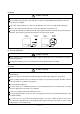
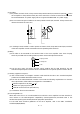
(5) Grounding (a) To prevent an electric shock, always connect the protective earth (PE) terminals (marked ) of the servo amplifier to the protective earth (PE) of the control box. Connect PE terminal of the control box to the NEUTRAL of a power supply. Be sure to ground the NEUTRAL of a power supply. (b) Do not connect two ground cables to the same protective earth (PE) terminal. Always connect the cables to the terminals one-to-one.
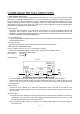
CONFORMANCE WITH UL/C-UL STANDARD (1) Servo amplifiers and servo motors used (Acquisition schedule) Use the servo amplifiers and servo motors which comply with the standard model. Servo amplifier Servo motor :MR-E-10A to MR-E-200A :HC-KFE HC-SFE (2) Installation Install a fan of 100CFM (2.8 m3/min) air flow 4 in (10.16 cm) above the servo amplifier or provide cooling of at least equivalent capability.
MEMO A - 10
CONTENTS 1. FUNCTIONS AND CONFIGURATION 1- 1 to 1-10 1.1 Introduction.............................................................................................................................................. 1- 1 1.2 Function block diagram .......................................................................................................................... 1- 2 1.3 Servo amplifier standard specifications ..............................................................................................
4. OPERATION 4- 1 to 4- 6 4.1 When switching power on for the first time.......................................................................................... 4- 1 4.2 Startup...................................................................................................................................................... 4- 2 4.2.1 Selection of control mode.................................................................................................................. 4- 2 4.2.
7.3 Manual mode 1 (simple manual adjustment)....................................................................................... 7- 7 7.3.1 Operation of manual mode 1 ........................................................................................................... 7- 7 7.3.2 Adjustment by manual mode 1 ....................................................................................................... 7- 7 7.4 Interpolation mode ...............................................................
13.2 Auxiliary equipment .......................................................................................................................... 13-21 13.2.1 Recommended wires .................................................................................................................... 13-21 13.2.2 No-fuse breakers, fuses, magnetic contactors........................................................................... 13-23 13.2.3 Power factor improving reactors ......................................
15. MR-E- AG SERVO AMPLIFIER COMPATIBLE WITH ANALOG INPUT 15- 1 to 15- 62 15.1. Functions and configuration.............................................................................................................. 15- 1 15.1.1 Introduction................................................................................................................................... 15- 1 15.1.2 Function block diagram ..................................................................................................
MEMO 6
1. FUNCTIONS AND CONFIGURATION 1. FUNCTIONS AND CONFIGURATION 1.1 Introduction The Mitsubishi MR-E series general-purpose AC servo is based on the MR-J2-Super series, and has the same high performance and limited functions. It has position control and internal speed control modes. Further, it can perform operation with the control modes changed, e.g. position/internal speed control.
1. FUNCTIONS AND CONFIGURATION 1.2 Function block diagram The function block diagram of this servo is shown below.
1. FUNCTIONS AND CONFIGURATION 1.3 Servo amplifier standard specifications Servo Amplifier MR-E- 10A 20A 40A 70A 100A 200A Power supply Item Voltage/frequency 3-phase 200 to 230VAC, 50/60Hz or 1-phase 230VAC, 50/60Hz 3-phase 200 to 230VAC, 50/60Hz Permissible voltage fluctuation 3-phase 200 to 230VAC: 170 to 253VAC 1-phase 230VAC: 207 to 253VAC 3-phase 170 to 253VAC Permissible frequency fluctuation Within 5% Power supply capacity Refer to Section12.
1. FUNCTIONS AND CONFIGURATION 1.4 Function list The following table lists the functions of this servo. For details of the functions, refer to the corresponding chapters and sections. Function (Note) Control mode Description Refer to Position control mode This servo is used as position control servo. P Section 3.1.1 Section 3.4.1 Section 4.2.2 Internal speed control mode This servo is used as internal speed control servo. S Section 3.1.2 Section 3.4.2 Section 4.2.
1. FUNCTIONS AND CONFIGURATION Function Alarm history clear Description Alarm history is cleared. (Note) Control mode Refer to P, S Parameter No. 16 If the input power supply voltage had reduced to cause an Restart after instantaneous alarm but has returned to normal, the servo motor can be power failure restarted by merely switching on the start signal. S Parameter No. 20 Command pulse selection Command pulse train form can be selected from among four different types. P Parameter No.
1. FUNCTIONS AND CONFIGURATION 1.5 Model code definition (1) Rating plate MITSUBISHI AC AC SERVO SERVO MODEL MR-E-40A POWER :400W INPUT :2.6A 3PH200-230V 50Hz : :2.6A3PH200-230V 60Hz Model OUTPUT:170V 0-360Hz SERIAL :XXXXYYYYY Rated output current Capacity Applicable power supply 2.
1. FUNCTIONS AND CONFIGURATION 1.7 Parts identification (1) MR-E-100A or less Name/Application Display The 5-digit, seven-segment LED shows the servo status and alarm number. Refer to Chapter6 Operation section Used to perform status display, diagnostic, alarm and parameter setting operations. MODE UP DOWN SET Used to set data. MODE SET Used to change the display or data in each mode. CN3 MITSUBISHI MR- Used to change the mode.
1. FUNCTIONS AND CONFIGURATION (2) MR-E-200A Name/Application Display The 5-digit, seven-segment LED shows the servo status and alarm number. Refer to Chapter6 Operation section Used to perform status display, diagnostic, alarm and parameter setting operations. MODE UP DOWN SET Used to set data. Chapter6 Used to change the display or data in each mode. Used to change the mode. Communication connector (CN3) Used to connect a command device (RS232C) and output analog monitor data.
1. FUNCTIONS AND CONFIGURATION 1.8 Servo system with auxiliary equipment WARNING To prevent an electric shock, always connect the protective earth (PE) terminal (terminal marked ) of the servo amplifier to the protective earth (PE) of the control box. (1) MR-E-100A or less (Note 2) 3-phase 200V to 230VAC power supply or 1-phase 230VAC power supply Refer to Options and auxiliary equipment Options and auxiliary equipment Refer to No-fuse breaker Section 13.2.2 Regenerative option Section 13.1.
1. FUNCTIONS AND CONFIGURATION (2) MR-E-200A 3-phase 200V to 230VAC power supply Options and auxiliary equipment Refer to Refer to Section 13.2.2 Regenerative option Magnetic contactor Section 13.2.2 Cables Section 13.2.1 Servo configuration software Section 13.1.4 Power factor improving reactor Section 13.2.3 No-fuse breaker Section 13.1.
2. INSTALLATION 2. INSTALLATION CAUTION Stacking in excess of the limited number of products is not allowed. Install the equipment to incombustibles. Installing them directly or close to combustibles will led to a fire. Install the equipment in a load-bearing place in accordance with this Instruction Manual. Do not get on or put heavy load on the equipment to prevent injury. Use the equipment within the specified environmental condition range.
2. INSTALLATION 2.2 Installation direction and clearances The equipment must be installed in the specified direction. Otherwise, a fault may occur. Leave specified clearances between the servo amplifier and control box inside walls or other equipment. CAUTION (1) Installation of one servo amplifier Control box Control box 40mm (1.6 in.) or more Servo amplifier 10mm (0.4 in.) or more MODE SET Wiring clearance 70mm (2.8 in.) 10mm (0.4 in.
2. INSTALLATION (3) Others When using heat generating equipment such as the regenerative brake option, install them with full consideration of heat generation so that the servo amplifier is not affected. Install the servo amplifier on a perpendicular wall in the correct vertical direction. 2.3 Keep out foreign materials (1) When installing the unit in a control box, prevent drill chips and wire fragments from entering the servo amplifier. (2) Prevent oil, water, metallic dust, etc.
2.
3. SIGNALS AND WIRING 3. SIGNALS AND WIRING WARNING Any person who is involved in wiring should be fully competent to do the work. Before starting wiring, switch power off, then wait for more than 10 minutes, and after the charge lamp has gone off, make sure that the voltage is safe in the tester or like. Otherwise, you may get an electric shock. Ground the servo amplifier and the servo motor securely. Do not attempt to wire the servo amplifier and servo motor until they have been installed.
3. SIGNALS AND WIRING 3.1 Standard connection example POINT Refer to Section 3.7.1 for the connection of the power supply system and to Section 3.8 for connection with the servo motor. 3.1.1 Position control mode (1) FX-10GM Positioning module FX-10GM Servo amplifier (Note 8) CN1 SVRDY COM2 COM2 SVEND COM4 PGO 1 2 12 11 14 13 7,17 24 8,18 VC 5 FPO 6 FP COM5 9,19 16 RP 15 RPO 3 CLR 4 COM3 RD VIN INP 11 1 10 VIN OP LG OPC VIN 1 21 14 2 1 PP SG NP 23 13 25 CR SG SD 5 13 Plate (Note 9) 2m(6.
3. SIGNALS AND WIRING Note: 1. To prevent an electric shock, always connect the protective earth (PE) terminal (terminal marked ) of the servo amplifier to the protective earth (PE) of the control box. 2. Connect the diode in the correct direction. If it is connected reversely, the servo amplifier will be faulty and will not output signals, disabling the emergency stop and other protective circuits. 3. The emergency stop switch (normally closed contact) must be installed. 4.
3. SIGNALS AND WIRING (2) AD75P (A1SD75P ) Positioning module AD75P (A1SD75P ) Servo amplifier (Note 9) 10m(32ft) max.
3. SIGNALS AND WIRING Note: 1. To prevent an electric shock, always connect the protective earth (PE) terminal (terminal marked ) of the servo amplifier to the protective earth (PE) of the control box. 2. Connect the diode in the correct direction. If it is connected reversely, the servo amplifier will be faulty and will not output signals, disabling the emergency stop and other protective circuits. 3. The emergency stop switch (normally closed contact) must be installed. 4.
3. SIGNALS AND WIRING (3) QD75D (differential driver) Positioning module QD75D READY RDY COM PGO5 PGO COM CLEAR CLEAR COM PULSE FPULSE F+ PULSE RPULSE R+ COM COM DOG FLS RLS STOP CHG PULSER A+ PULSER APULSER B+ PULSER B- Servo amplifier (Note 9) 10m(32ft) max.
3. SIGNALS AND WIRING Note: 1. To prevent an electric shock, always connect the protective earth (PE) terminal (terminal marked ) of the servo amplifier to the protective earth (PE) of the control box. 2. Connect the diode in the correct direction. If it is connected reversely, the servo amplifier will be faulty and will not output signals, disabling the emergency stop and other protective circuits. 3. The emergency stop switch (normally closed contact) must be installed. 4.
3. SIGNALS AND WIRING 3.1.2 Internal speed control mode Servo amplifier (Note 8) CN1 10m(32ft) max.
3. SIGNALS AND WIRING 3.2 Internal connection diagram of servo amplifier The following is the internal connection diagram where the signal assignment has been made in the initial status in each control mode. Servo amplifier (Note) (Note) External power supply 24VDC P S CN1 CN1 P S VIN VIN 1 10 INP SA CR ST2 5 Approx. 4.7k 11 RD RD 9 ALM ALM 12 ZSP ZSP Approx. 4.
3. SIGNALS AND WIRING 3.3 I/O signals 3.3.1 Connectors and signal arrangements POINT The pin configurations of the connectors are as viewed from the cable connector wiring section. Refer to the next page for CN1 signal assignment.
3. SIGNALS AND WIRING (2) CN1 signal assignment The signal assignment of connector changes with the control mode as indicated below; For the pins which are given parameter No.s in the related parameter column, their signals can be changed using those parameters. Connector Pin No. (Note1) I/O 1 2 CN1 (Note2) I/O Signals in control modes P P/S S VIN VIN VIN Related parameter OPC OPC 3 I RES RES/ST1 ST1 No.43 to 48 4 I SON SON SON No.43 to 48 5 I CR LOP ST2 No.
3.
3. SIGNALS AND WIRING 3.3.2 Signal explanations For the I/O interfaces (symbols in I/O column in the table), refer to Section 3.6.2. In the control mode field of the table P : Position control mode, S: Internal speed control mode : Denotes that the signal may be used in the initial setting status. : Denotes that the signal may be used by setting the corresponding parameter among parameters 43 to 49. The pin No.s in the connector pin No. column are those in the initial status.
3. SIGNALS AND WIRING Signal ConnecSymbol tor pin No. Internal torque limit selection TL1 Forward rotation start ST1 Reverse rotation start ST2 SP1 Speed selection 2 SP2 Proportion control When using this signal, make it usable by making the setting of parameter No. 43 to 48. (Refer to (5), Section 3.4.1.
3. SIGNALS AND WIRING Signal Emergency stop Clear ConnecSymbol tor pin No. Functions/Applications I/O division EMG CN1-8 Disconnect EMG-SG to bring the servo motor to emergency stop state, in which the servo is switched off and the dynamic brake is operated. Connect EMG-SG in the emergency stop state to reset that state. DI-1 CR CN1-5 Connect CR-SG to clear the position control counter droop pulses on its leading edge. The pulse width should be 10ms or more. When the parameter No.
3. SIGNALS AND WIRING (2) Output signals Signal Trouble ConnecSymbol tor pin No. ALM CN1-9 Functions/Applications I/O division ALM-SG are disconnected when power is switched off or the protective circuit is activated to shut off the base circuit. Without alarm, ALM-SG are connected within 1 after power on. DO-1 Ready RD CN1-11 RD-SG are connected when the servo is switched on and the servo amplifier is ready to operate.
3. SIGNALS AND WIRING Signal Alarm code ConnecSymbol tor pin No. ACD 0 ACD 1 ACD 2 I/O division Functions/Applications To use this signal, set " 1 " in parameter No.49. This signal is output when an alarm occurs. When there is no alarm, respective ordinary signals (RD, INP, SA, ZSP) are output. Alarm codes and alarm names are listed below: (Note) Alarm code CN1 CN1 CN1 12 Pin 11 Pin 10 Pin 0 0 0 0 1 0 0 0 1 0 1 1 1 1 0 1 0 1 0 0 1 Alarm display Name 88888 Watchdog AL.
3. SIGNALS AND WIRING Connector pin No. Symbol Encoder Z-phase pulse (Open collector) OP CN1-21 Outputs the zero-point signal of the encoder. One pulse is output per servo motor revolution. OP and LG are connected when the zero-point position is reached. (Negative logic) The minimum pulse width is about 400 s. For home position return using this pulse, set the creep speed to 100r/min. or less.
3. SIGNALS AND WIRING 3.4 Detailed description of the signals 3.4.1 Position control mode (1) Pulse train input (a) Input pulse waveform selection Encoder pulses may be input in any of three different forms, for which positive or negative logic can be chosen. Set the command pulse train form in parameter No. 21. Arrow or in the table indicates the timing of importing a pulse train. A- and B-phase pulse trains are imported after they have been multiplied by 4.
3. SIGNALS AND WIRING (b) Connections and waveforms 1) Open collector system Connect as shown below: Servo amplifier External power supply 24VDC OPC PP Approx. 1.2k NP Approx. 1.2k SG SD The explanation assumes that the input waveform has been set to the negative logic and forward and reverse rotation pulse trains (parameter No.21 has been set to 0010). The waveforms in the table in (a), (1) of this section are voltage waveforms of PP and NP based on SG.
3. SIGNALS AND WIRING 2) Differential line driver system Connect as shown below: Servo amplifier PP PG NP NG SD The explanation assumes that the input waveform has been set to the negative logic and forward and reverse rotation pulse trains (parameter No.21 has been set to 0010). For the differential line driver, the waveforms in the table in (a), (1) of this section are as follows. The waveforms of PP, PG, NP and NG are based on that of the ground of the differential line driver.
3. SIGNALS AND WIRING (2) In-position (INP) PF-SG are connected when the number of droop pulses in the deviation counter falls within the preset in-position range (parameter No. 5). INP-SG may remain connected when low-speed operation is performed with a large value set as the in-position range.
3. SIGNALS AND WIRING (5) Torque limit (a) Torque limit and torque By setting parameter No. 28 (internal torque limit 1), torque is always limited to the maximum value during operation. A relationship between the limit value and servo motor torque is shown below. Torque Max. torque 0 0 100 Torque limit value [%] (b) Torque limit value selection When internal torque limit selection (TL1) is made usable by parameter No. 43 to 48, internal torque limit 2 (parameter No. 76) can be selected.
3. SIGNALS AND WIRING 3.4.2 Internal speed control mode (1) Speed setting (a) Speed command and speed The servo motor is run at the speeds set in the parameters.
3. SIGNALS AND WIRING (b) Speed selection 1 (SP1), speed selection 2 (SP2), speed selection 3 (SP3) and speed command value By making speed selection 1 (SP1), speed selection 2 (SP2) and speed selection 3 (SP3) usable by setting of parameter No. 43 to 47, you can choose the speed command values of internal speed commands 1 to 7. (Note) External input signals Speed command value SP3 SP2 SP1 0 0 0 Internal speed command 1 (parameter No. 8) 0 0 1 Internal speed command 1 (parameter No.
3. SIGNALS AND WIRING 3.4.3 Position/internal speed control change mode Set "0001" in parameter No. 0 to switch to the position/internal speed control change mode. This function is not available in the absolute position detection system. (1) Control change (LOP) Use control change (LOP) to switch between the position control mode and the internal speed control mode from an external contact.
3. SIGNALS AND WIRING (3) Internal speed setting in speed control mode (a) Speed command and speed The servo motor is run at the speed set in parameter No. 8 (internal speed command 1) the forward rotation start signal (ST1) and reverse rotation start signal (ST2) are as in (a), (1) in section 3.4.2.
3. SIGNALS AND WIRING 3.5 Alarm occurrence timing chart When an alarm has occurred, remove its cause, make sure that the operation signal is not being input, ensure safety, and reset the alarm before restarting operation. CAUTION When an alarm occurs in the servo amplifier, the base circuit is shut off and the servo motor is coated to a stop. Switch off the power supply in the external sequence.
3. SIGNALS AND WIRING 3.6 Interfaces 3.6.1 Common line The following diagram shows the power supply and its common line. CN1 CN1 RA External power supply 24VDC VIN ALM, etc. DO-1 SON, etc. DI-1 SG OPC (Note) PG NG PP NP SG SG Isolated OP LG LA etc. Differential line driver output 35mA max. LAR etc. LG SD MO1 MO2 CN3 Analog monitor output LG SD SD TXD RXD RS-232C Servo motor encoder MR MRR Servo motor CN2 LG SM SD Ground Note: For the open collection pulse train input.
3. SIGNALS AND WIRING 3.6.2 Detailed description of the interfaces This section gives the details of the I/O signal interfaces (refer to I/O Division in the table) indicated in Sections 3.3.2. Refer to this section and connect the interfaces with the external equipment. (1) Digital input interface DI-1 Give a signal with a relay or open collector transistor. Servo amplifier External power supply 24VDC 200mA or more R: Approx. 4.7 VIN SON, etc.
3. SIGNALS AND WIRING (b) Lamp load Servo amplifier VIN External power supply 24VDC 10% R ALM, etc. SG (3) Pulse train input interface DI-2 Provide a pulse train signal in the open collector or differential line driver system. (a) Open collector system 1) Interface Servo amplifier Max. input pulse frequency 200kpps VIN About 1.2k External power supply 24VDC PP, NP SG SD 2) Conditions of the input pulse tc PP tHL tLH tHL 0.2 s tc 2 s tF 3 s 0.9 0.
3. SIGNALS AND WIRING (b) Differential line driver system 1) Interface Servo amplifier Max. input pulse frequency 500kpps Am26LS31 or equivalent PP(NP) PG(NG) About 100 SD 2) Conditions of the input pulse tHL tc PP PG tLH tHL 0.1 s tc 1 s tF 3 s 0.9 0.1 tc tLH tF NP NG (4) Encoder pulse output (a) Open collector system Interface Max.
3. SIGNALS AND WIRING (b) Differential line driver system 1) Interface Max. output current: 35mA Servo amplifier Servo amplifier LA (LB, LZ) Am26LS32 or equivalent LA (LB, LZ) 100 150 LAR (LBR, LZR) LAR (LBR, LZR) LG SD SD 2) Output pulse Servo motor CCW rotation LA LAR T LB LBR /2 LZ signal varies 3/8T on its leading edge. LZ LZR 400 s or more OP (5) Analog output Output voltage 10V Max.1mA Max.
3. SIGNALS AND WIRING 3.7 Input power supply circuit CAUTION When the servo amplifier has become faulty, switch power off on the servo amplifier power side. Continuous flow of a large current may cause a fire. Use the trouble signal to switch power off. Otherwise, a regenerative brake transistor fault or the like may overheat the regenerative brake resistor, causing a fire. POINT The power supply connector (CNP1) is optional. Purchase it without fail. 3.7.
3. SIGNALS AND WIRING (2) For 1-phase 230VAC power supply Emergency OFF stop ON RA MC MC SK NFB MC CNP1Servo amplifier L1 Power supply 1-phase 230VAC L2 L3 P (Note) D C EMG Emergency stop Servo-on SON SG VIN ALM RA External power Trouble supply 24VDC SG Note: To use the built-in regenerative resistor, be sure to connect across P and D of the power supply connector (CNP1). 3.7.2 Terminals Refer to Section 11.1 (4) for the signal arrangement.
3. SIGNALS AND WIRING 3.7.3 Power-on sequence (1) Power-on procedure 1) Always wire the power supply as shown in above Section 3.7.1 using the magnetic contactor with the power supply (three-phase 200V: L1, L2, L3, single-phase 230V: L1, L2). Configure up an external sequence to switch off the magnetic contactor as soon as an alarm occurs. 2) The servo amplifier can accept the servo-on signal (SON) 2s or more after the power supply is switched on.
3. SIGNALS AND WIRING 3.8 Connection of servo amplifier and servo motor 3.8.1 Connection instructions WARNING Insulate the connections of the power supply terminals to prevent an electric shock. CAUTION Connect the wires to the correct phase terminals (U, V, W) of the servo amplifier and servo motor. Otherwise, the servo motor will operate improperly. Do not connect AC power supply directly to the servo motor. Otherwise, a fault may occur.
3. SIGNALS AND WIRING Servo motor Connection diagram Servo amplifier Servo motor CNP2 U (Red) U V (White) V W (Black) W Motor (Green) (Note 1) 24VDC HC-KFE13 (B) to 73 (B) B1 (Note2) B2 Electromagnetic brake EMG To be shut off when servo on signal switches off or by alarm signal CN2 Encoder Encoder cable Note:1. To prevent an electric shock, always connect the protective earth (PE) terminal of the servo amplifier to the protective earth (PE) of the control box. 2.
3. SIGNALS AND WIRING 3.8.3 I/O terminals (1) HC-KFE series Encoder connector signal arrangement Power supply lead 4-AWG19 0.3m (0.98ft.) a Encoder cable 0.3m (0.98ft.
3. SIGNALS AND WIRING (2) HC-SFE series Servo motor side connectors Servo motor For power supply For encoder The connector CE05-2A22- HC-SFE52(B) to 152(B) 23PD-B CE05-2A24- HC-SFE202(B) Electromagnetic brake connector MS3102A2029P 17PD-B for power is shared.
3. SIGNALS AND WIRING 3.9 Servo motor with electromagnetic brake Configure the electromagnetic brake operation circuit so that it is activated not only by the servo amplifier signals but also by an external emergency stop signal. Contacts must be open when servo-on signal is off or when an alarm (trouble) is present and when an electromagnetic brake signal. Circuit must be opened during emergency stop signal.
3. SIGNALS AND WIRING (3) Timing charts (a) Servo-on signal command (from controller) ON/OFF Tb [ms] after the servo-on (SON) signal is switched off, the servo lock is released and the servo motor coasts. If the electromagnetic brake is made valid in the servo lock status, the brake life may be shorter. Therefore, when using the electromagnetic brake in a vertical lift application or the like, set Tb to about the same as the electromagnetic brake operation delay time to prevent a drop.
3.
3. SIGNALS AND WIRING 3.10 Grounding WARNING Ground the servo amplifier and servo motor securely. To prevent an electric shock, always connect the protective earth (PE) terminal of the servo amplifier with the protective earth (PE) of the control box. The servo amplifier switches the power transistor on-off to supply power to the servo motor. Depending on the wiring and ground cablerouting, the servo amplifier may be affected by the switching noise (due to di/dt and dv/dt) of the transistor.
3. SIGNALS AND WIRING 3.11 Servo amplifier connectors (CNP1, CNP2) wiring method (When MR-ECPN1-B and MR-ECPN2-B of an option are used.) (1) Termination of the cables Solid wire: After the sheath has been stripped, the cable can be used as it is. (Cable size: 0.2 to 2.5mm2) 8 to 9 mm Twisted wire: Use the cable after stripping the sheath and twisting the core. At this time, take care to avoid a short caused by the loose wires of the core and the adjacent pole.
3. SIGNALS AND WIRING (2) Inserting the cable into the connector (a) Applicable flat-blade screwdriver dimensions Always use the screwdriver shown here to do the work. [Unit: mm] (22) 3 0.6 (R0.3) 3 to 3.5 (R0.3) (b) When using the flat-blade screwdriver - part 1 1) Insert the screwdriver into the square hole. Insert it along the top of the square hole to insert it smoothly. 2) If inserted properly, the screwdriver is held. 3) With the screwdriver held, insert the cable in the direction of arrow.
3. SIGNALS AND WIRING (c) When using the flat-blade screwdriver - part 2 1) Insert the screwdriver into the square window at top of the connector. 2) Push the screwdriver in the direction of arrow. 4) Releasing the screwdriver connects the cable. 3 - 47 3) With the screwdriver pushed, insert the cable in the direction of arrow. (Insert the cable as far as it will go.
3. SIGNALS AND WIRING 3.12 Instructions for the 3M connector When fabricating an encoder cable or the like, securely connect the shielded external conductor of the cable to the ground plate as shown in this section and fix it to the connector shell. External conductor Sheath Core Sheath External conductor Pull back the external conductor to cover the sheath Strip the sheath.
4. OPERATION 4. OPERATION 4.1 When switching power on for the first time Before starting operation, check the following: (1) Wiring (a) A correct power supply is connected to the power input terminals (L1, L2, L3) of the servo amplifier. (b) The servo motor power supply terminals (U, V, W) of the servo amplifier match in phase with the power input terminals (U, V, W) of the servo motor.
4. OPERATION 4.2 Startup WARNING Do not operate the switches with wet hands. You may get an electric shock. CAUTION Before starting operation, check the parameters. Some machines may perform unexpected operation. During power-on for some after power-off, do not touch or close a parts (cable etc.) to the servo amplifier heat sink, regenerative brake resistor, the servo motor, etc. Their temperatures may be high and you may get burnt or a parts may damaged.
4. OPERATION (4) Servo-on Switch the servo-on in the following procedure: 1) Switch on power supply. 2) Switch on the servo-on signal (SON). When placed in the servo-on status, the servo amplifier is ready to operate and the servo motor is locked. (5) Command pulse input Entry of a pulse train from the positioning device rotates the servo motor. At first, run it at low speed and check the rotation direction, etc. If it does not run in the intended direction, check the input signal.
4. OPERATION 4.2.3 Internal speed control mode (1) Power on 1) Switch off the servo-on (SON) signal. 2) When circuit power is switched on, the display shows "r (servo motor speed)", and in two second later, shows data. (2) Test operation Using jog operation in the test operation mode, make sure that the servo motor operates. (Refer to Section 6.8.2.) (3) Parameter setting Set the parameters according to the structure and specifications of the machine.
4. OPERATION (6) Stop In any of the following statuses, the servo amplifier interrupts and stops the operation of the servo motor: Refer to Section 3.9, (2) for the servo motor equipped with electromagnetic brake. Note that simultaneous ON or simultaneous OFF of stroke end (LSP, LSN) OFF and forward rotation start (ST1) or reverse rotation start (ST2) signal has the same stop pattern as described below. (a) Servo-on (SON) OFF The base circuit is shut off and the servo motor coasts.
4.
5. PARAMETERS 5. PARAMETERS CAUTION Never adjust or change the parameter values extremely as it will make operation instable. 5.1 Parameter list 5.1.1 Parameter write inhibit POINT After setting the parameter No. 19 value, switch power off, then on to make that setting valid. This servo amplifier, its parameters are classified into the basic parameters (No. 0 to 19), expansion parameters 1 (No. 20 to 49) and expansion parameters 2 (No.50 to 84) according to their safety aspects and frequencies of use.
5. PARAMETERS 5.1.2 Lists POINT For any parameter whose symbol is preceded by *, set the parameter value and switch power off once, then switch it on again to make that parameter setting valid. The symbols in the control mode column of the table indicate the following modes: P : Position control mode S : Internal speed control mode (1) Item list Basic parameters No.
5. PARAMETERS No.
5. PARAMETERS No.
5. PARAMETERS (2) Details list Class No. Symbol 0 *STY Name and function Control mode, regenerative brake option selection Used to select the control mode and regenerative brake option. Initial value 100W : 0000 Unit Setting Control range mode Refer to P S Name and Basic parameters Select the control mode.
5. PARAMETERS Class No. Symbol 2 ATU Name and function Auto tuning Used to selection the response level, etc. for execution of auto tuning. Refer to Chapter 7. 0 Initial value 0105 Unit Setting Control range mode Refer to P S Name and function 0 column.
5. PARAMETERS No. Symbol 5 INP 6 PG1 7 PST Name and function In-position range Used to set the in-position signal (INP) output range in the command pulse increments prior to electronic gear calculation. Position loop gain 1 Used to set the gain of position loop. Increase the gain to improve trackability in response to the position command. When auto turning mode 1,2 is selected, the result of auto turning is automatically used.
5. PARAMETERS Class No. Symbol 9 SC2 Internal speed command 2 Used to set speed 2 of internal speed commands. 10 SC3 Internal speed command 3 Used to set speed 3 of internal speed commands. 11 STA Acceleration time constant Used to set the acceleration time required to reach the rated speed from 0r/min in response to the internal speed commands 1 to 7.
5. PARAMETERS Class No. Symbol 14 Name and function Initial value For manufacturer setting Don’t change this value by any means. 0 15 *SNO Station number setting Used to specify the station number for serial communication. Always set one station to one axis of servo amplifier. If one station number is set to two or more stations, normal communication cannot be made.
5. PARAMETERS Class No. Symbol 18 Initial value Name and function *DMD Status display selection Used to select the status display shown at power-on. Unit 0000 Setting Control range mode Refer to P S Name and 0 0 function column.
5. PARAMETERS Class No. Symbol 20 *OP2 Name and function Function selection 2 Used to select restart after instantaneous power failure, servo lock at a stop in internal speed control mode, and slight vibration suppression control. Initial value 0000 Unit Setting Control range mode Refer to Name and function column. Restart after instantaneous power failure If the input power supply voltage had reduced in the internal speed control mode to stop the servo motor due to the undervoltage alarm (AL.
5. PARAMETERS Class No. Symbol 22 *OP4 Name and function Function selection 4 Used to select stop processing at forward rotation stroke end (LSP) reverse rotation stroke end (LSN) off and choose TLC/VLC output. Initial value Unit 0000 Refer to P S Name and function 0 0 0 Expansion parameters 1 Setting Control range mode column. How to make a stop when forward rotation stroke end (LSP) reverse rotation stroke end (LSN) is valid. (Refer to Section 5.2.3.
5. PARAMETERS Class No. Symbol Expansion parameters 1 27 *ENR Name and function Encoder output pulses Used to set the encoder pulses (A-phase or B-phase) output by the servo amplifier. Set the value 4 times greater than the A-phase or B-phase pulses. You can use parameter No. 54 to choose the output pulse designation or output division ratio setting. The number of A/B-phase pulses actually output is 1/4 times greater than the preset number of pulses. The maximum output frequency is 1.
5. PARAMETERS Expansion parameters 1 Class No. Symbol 35 PG2 36 VG1 37 VG2 38 VIC 39 VDC 40 41 Name and function Position loop gain 2 Used to set the gain of the position loop. Set this parameter to increase the position response to level load disturbance. Higher setting increases the response level but is liable to generate vibration and/or noise. When auto tuning mode 1,2 and interpolation mode is selected, the result of auto tuning is automatically used.
5. PARAMETERS Class No. Symbol 42 *DI1 Name and function Input signal selection 1 Used to assign the control mode changing signal input pins and to set the clear (CR). 0002 Unit Setting Control range mode Refer to Name and function 0 0 Expansion parameters 1 Initial value column. Control change (LOP) input pin assignment Used to set the control mode change signal input connector pins. Note that this parameter is made valid when parameter No.
5. PARAMETERS Class No. Symbol 43 *DI2 Name and function Input signal selection 2 (CN1-4) Allows any input signal to be assigned to CN1-pin 4. Note that the setting digit and assigned signal differ according to the control mode. 0111 Unit Setting Control range mode Refer to Name and function column. 0 0 Position Input signals of control mode CN1-pin 4 Internal speed selected. control mode Signals that may be assigned in each control mode are indicated below by their symbols.
5. PARAMETERS Class No. Symbol 44 *DI3 Name and function Input signal selection 3 (CN1-3) Allows any input signal to be assigned to CN1-pin 3. The assignable signals and setting method are the same as in input signal selection 2 (parameter No. 43). Initial value 0882 Unit Setting Control range mode Refer to P S Name and function column. 0 0 Position control mode Internal speed control mode Input signals of CN1-pin 3 selected. This parameter is unavailable when parameter No.
5. PARAMETERS Class No. Symbol 47 *DI6 Name and function Input signal selection 6 (CN1-7) Allows any input signal to be assigned to CN1-pin 7. The assignable signals and setting method are the same as in input signal selection 2 (parameter No. 43). Initial value 0000 Expansion parameters 1 Refer to P S and function column. Position control mode Internal speed control mode Input signals of CN1-pin 7 selected. This parameter is unavailable when parameter No.
5. PARAMETERS Class No. Symbol 49 *DO1 Initial value Name and function Output signal selection 1 Used to select the connector pins to output the alarm code and warning (WNG). Setting range Control mode Refer to P S Name and function 0 0 column. Setting of alarm code output Connector pins Set value CN1-10 CN1-11 CN1-12 0 INP or SA RD ZSP Alarm code is output at alarm occurrence.
5. PARAMETERS Class No. Symbol 50 51 *OP6 Initial value Name and function For manufacturer setting Don’t change this value by any means. 0000 Function selection 6 Used to select the operation to be performed when the reset (RES) switches on. 0000 0 Unit Setting Control range mode Refer to P S Name and function 0 0 column.
5. PARAMETERS Class No. Symbol 55 *OPA Initial value Name and function Function selection A Used to select the position command acceleration/deceleration time constant (parameter No. 7) control system. 0 0 Unit 0000 Setting Control range mode Refer to P Name and function 0 column.
5. PARAMETERS Class No. Symbol 60 LPF Name and function Low-pass filter/adaptive vibration suppression control Used to selection the low-pass filter and adaptive vibration suppression control. (Refer to Chapter 8.) Initial value Unit 0000 Setting Control range mode Refer to P S Name and function 0 column. Low-pass filter selection 0: Valid (Automatic adjustment) 1: Invalid VG2 setting 10 When you choose "valid", 2 (1 GD2 setting 0.1) [Hz] bandwidth filter is set automatically.
5. PARAMETERS Class No. Symbol 65 *CDP Name and function Gain changing selection Used to select the gain changing condition. (Refer to Section 8.5.) Initial value Unit 0000 Setting Control range mode Refer to P S Name and 0 0 0 function column. Expansion parameters 2 Gain changing selection Gains are changed in accordance with the settings of parameters No.
5. PARAMETERS Expansion parameters 2 Class No. Symbol Name and function Initial value 73 SC5 Internal speed command 5 Used to set speed 5 of internal speed commands. 300 74 SC6 Internal speed command 6 Used to set speed 6 of internal speed commands. 500 75 SC7 Internal speed command 7 Used to set speed 7 of internal speed commands. 800 76 TL2 Internal torque limit 2 Set this parameter to limit servo motor torque on the assumption that the maximum torque is 100[%].
5. PARAMETERS 5.2 Detailed description 5.2.1 Electronic gear CAUTION Wrong setting can lead to unexpected fast rotation, causing injury. POINT 1 CMX 50. 50 CDV If the set value is outside this range, noise may be generated during acceleration/ deceleration or operation may not be performed at the preset speed and/or acceleration/deceleration time constants. The following specification symbols are required to calculate the electronic gear.
5. PARAMETERS (2) Conveyor setting example For rotation in increments of 0.01 per pulse Servo motor 10000 [pulse/rev] Machine specifications Table Table : 360 /rev Reduction ratio: n 1/18 Servo motor resolution: Pt CMX CDV Pt 0.01 10000 [pulses/rev] 10000 1/18 360 100 20 Timing belt : 4/64 5 1 Hence, set 5 to CMX and 1 to CDV. 5.2.2 Analog monitor The servo status can be output to two channels in terms of voltage.
5. PARAMETERS (2) Set content The servo amplifier is factory-set to output the servo motor speed to Analog monitor 1 (MO1) and the torque to Analog monitor 2 (MO2). The setting can be changed as listed below by changing the parameter No.17 value: Refer to Appendix 2 for the measurement point. Setting 0 Output item Servo motor speed Description Setting 6 CCW direction 8[V] Output item Droop pulses ( 10V/128pulse) Description 10[V] CCW direction 128[pulse] Max. speed 0 0 Max.
Command pulse Command pulse frequency Droop pulse Position control Speed command 5 - 28 Servo motor speed Differential Speed control Current command Torque Current control Encoder M Servo Motor Position feedback Current feedback PWM Current encoder Bus voltage 5.
5. PARAMETERS 5.2.3 Using forward/reverse rotation stroke end to change the stopping pattern The stopping pattern is factory-set to make a sudden stop when the forward/reverse rotation stroke end is made valid. A slow stop can be made by changing the parameter No. 22 value. Parameter No.22 Setting 0 (initial value) Stopping method Sudden stop Position control mode : Motor stops with droop pulses cleared. Internal speed control mode : Motor stops at deceleration time constant of zero.
5. PARAMETERS 5.2.5 Position smoothing By setting the position command acceleration/deceleration time constant (parameter No.7), you can run the servo motor smoothly in response to a sudden position command. The following diagrams show the operation patterns of the servo motor in response to a position command when you have set the position command acceleration/deceleration time constant. Choose the primary delay or linear acceleration/deceleration in parameter No. 55 according to the machine used.
6. DISPLAY AND OPERATION 6. DISPLAY AND OPERATION 6.1 Display flowchart Use the display (5-digit, 7-segment LED) on the front panel of the servo amplifier for status display, parameter setting, etc. Set the parameters before operation, diagnose an alarm, confirm external sequences, and/or confirm the operation status. Press the "MODE" "UP" or "DOWN" button once to move to the next screen. To refer to or set the expansion parameters, make them valid with parameter No. 19 (parameter write disable).
6. DISPLAY AND OPERATION 6.2 Status display The servo status during operation is shown on the 5-digit, 7-segment LED display. Press the "UP" or "DOWN" button to change display data as desired. When the required data is selected, the corresponding symbol appears. Press the "SET" button to display its data. At only power-on, however, data appears after the symbol of the status display selected in parameter No. 18 has been shown for 2.
6. DISPLAY AND OPERATION 6.2.2 Status display list The following table lists the servo statuses that may be shown: Name Symbol Unit Description Cumulative feedback pulses C pulse Servo motor speed r r/min Feedback pulses from the servo motor encoder are counted and displayed. The value in excess of 99999 is counted, bus since the servo amplifier display is five digits, it shows the lower five digits of the actual value. Press the "SET" button to reset the display value to zero.
6. DISPLAY AND OPERATION Display range Name Symbol Unit Description Within one-revolution position high Cy2 100 pulse The within one-revolution position is displayed in 100 pulse increments of the encoder. The value returns to 0 when it exceeds the maximum number of pulses. The value is incremented in the CCW direction of rotation. 0 to 1310 Load inertia moment ratio dC 0.1 Times The estimated ratio of the load inertia moment to the servo motor shaft inertia moment is displayed. 0.0 to 300.
6. DISPLAY AND OPERATION 6.3 Diagnostic mode Name Display Description Not ready. Indicates that the servo amplifier is being initialized or an alarm has occurred. Sequence Ready. Indicates that the servo was switched on after completion of initialization and the servo amplifier is ready to operate. External I/O signal display Indicates the ON-OFF states of the external I/O signals. The upper segments correspond to the input signals and the lower segments to the output signals.
6. DISPLAY AND OPERATION 6.4 Alarm mode The current alarm, past alarm history and parameter error are displayed. The lower 2 digits on the display indicate the alarm number that has occurred or the parameter number in error. Display examples are shown below. Name Display Description Indicates no occurrence of an alarm. Current alarm Indicates the occurrence of overvoltage (AL.33). Flickers at occurrence of the alarm. Indicates that the last alarm is overload 1 (AL.50).
6. DISPLAY AND OPERATION 6.5 Parameter mode The parameters whose abbreviations are marked* are made valid by changing the setting and then switching power off once and switching it on again. Refer to Section 5.1.2. (1) Operation example The following example shows the operation procedure performed after power-on to change the control mode (parameter No. 0) to the Internal speed control mode. Using the "MODE" button, show the basic parameter screen. The parameter number is displayed.
6. DISPLAY AND OPERATION 6.6 External I/O signal display The ON/OFF states of the digital I/O signals connected to the servo amplifier can be confirmed. (1) Operation Call the display screen shown after power-on. Using the "MODE" button, show the diagnostic screen. Press UP once.
6.
6. DISPLAY AND OPERATION 6.7 Output signal (DO) forced output POINT When the servo system is used in a vertical lift application, turning on the electromagnetic brake interlock (MBR) after assigning it to pin CN1-12 will release the electromagnetic brake, causing a drop. Take drop preventive measures on the machine side. The output signal can be forced on/off independently of the servo status. This function is used for output signal wiring check, etc.
6. DISPLAY AND OPERATION 6.8 Test operation mode CAUTION The test operation mode is designed to confirm servo operation and not to confirm machine operation. In this mode, do not use the servo motor with the machine. Always use the servo motor alone. If any operational fault has occurred, stop operation using the emergency stop (EMG) signal. POINT The servo configuration software is required to perform positioning operation. Test operation cannot be performed if the servo-on (SON) is not turned OFF. 6.
6. DISPLAY AND OPERATION 6.8.2 Jog operation Jog operation can be performed when there is no command from the external command device. (1) Operation Connect EMG-SG to start jog operation to use the internal power supply. Hold down the "UP" or "DOWN" button to run the servo motor. Release it to stop. When using the servo configuration software, you can change the operation conditions.
6. DISPLAY AND OPERATION 6.8.3 Positioning operation POINT The servo configuration software is required to perform positioning operation. Positioning operation can be performed once when there is no command from the external command device. (1) Operation Connect EMG-SG to start positioning operation to use the internal power supply. Click the "Forward" or "Reverse" button on the servo configuration software starts the servo motor, which will then stop after moving the preset travel distance.
6. DISPLAY AND OPERATION 6.8.4 Motor-less operation Without connecting the servo motor, you can provide output signals or monitor the status display as if the servo motor is running in response to external input signals. This operation can be used to check the sequence of a host programmable controller or the like. (1) Operation After turning off the signal across SON-SG, choose motor-less operation. After that, perform external operation as in ordinary operation.
7. GENERAL GAIN ADJUSTMENT 7. GENERAL GAIN ADJUSTMENT 7.1 Different adjustment methods 7.1.1 Adjustment on a single servo amplifier The gain adjustment in this section can be made on a single servo amplifier. For gain adjustment, first execute auto tuning mode 1. If you are not satisfied with the results, execute auto tuning mode 2, manual mode 1 and manual mode 2 in this order. (1) Gain adjustment mode explanation Gain adjustment mode Parameter No.
7. GENERAL GAIN ADJUSTMENT (2) Adjustment sequence and mode usage START Usage Interpolation made for 2 or more axes? Yes Interpolation mode No Operation Allows adjustment by merely changing the response level setting. First use this mode to make adjustment. Auto tuning mode 1 Operation Yes No OK? No Operation OK? Used when the conditions of auto tuning mode 1 are not met and the load inertia moment ratio could not be estimated properly, for example.
7. GENERAL GAIN ADJUSTMENT 7.2 Auto tuning 7.2.1 Auto tuning mode The servo amplifier has a real-time auto tuning function which estimates the machine characteristic (load inertia moment ratio) in real time and automatically sets the optimum gains according to that value. This function permits ease of gain adjustment of the servo amplifier. (1) Auto tuning mode 1 The servo amplifier is factory-set to the auto tuning mode 1.
7. GENERAL GAIN ADJUSTMENT 7.2.2 Auto tuning mode operation The block diagram of real-time auto tuning is shown below. Load inertia moment Automatic setting Command Encoder Control gains PG1,VG1 PG2,VG2,VIC Current control Servo motor Current feedback Set 0 or 1 to turn on. Gain table Switch Load inertia moment ratio estimation section Position/speed feedback Speed feedback Parameter No. 34 Load inertia moment ratio estimation value Parameter No.
7. GENERAL GAIN ADJUSTMENT 7.2.3 Adjustment procedure by auto tuning Since auto tuning is made valid before shipment from the factory, simply running the servo motor automatically sets the optimum gains that match the machine. Merely changing the response level setting value as required completes the adjustment. The adjustment procedure is as follows. Auto tuning adjustment Acceleration/deceleration repeated Yes Load inertia moment ratio estimation value stable? No Auto tuning conditions not satisfied.
7. GENERAL GAIN ADJUSTMENT 7.2.4 Response level setting in auto tuning mode Set the response (The first digit of parameter No.2) of the whole servo system. As the response level setting is increased, the trackability and settling time for a command decreases, but a too high response level will generate vibration. Hence, make setting until desired response is obtained within the vibrationfree range.
7. GENERAL GAIN ADJUSTMENT 7.3 Manual mode 1 (simple manual adjustment) If you are not satisfied with the adjustment of auto tuning, you can make simple manual adjustment with three parameters. 7.3.1 Operation of manual mode 1 In this mode, setting the three gains of position control gain 1 (PG1), speed control gain 2 (VG2) and speed integral compensation (VIC) automatically sets the other gains to the optimum values according to these gains.
7. GENERAL GAIN ADJUSTMENT (c)Adjustment description 1) Speed control gain 2 (parameter No. 37) This parameter determines the response level of the speed control loop. Increasing this value enhances response but a too high value will make the mechanical system liable to vibrate.
7. GENERAL GAIN ADJUSTMENT (c) Adjustment description 1) Position control gain 1 (parameter No. 6) This parameter determines the response level of the position control loop. Increasing position control gain 1 improves trackability to a position command but a too high value will make overshooting liable to occur at the time of settling.
7. GENERAL GAIN ADJUSTMENT 7.4 Interpolation mode The interpolation mode is used to match the position control gains of the axes when performing the interpolation operation of servo motors of two or more axes for an X-Y table or the like. In this mode, the position control gain 2 and speed control gain 2 which determine command trackability are set manually and the other parameter for gain adjustment are set automatically.
8. SPECIAL ADJUSTMENT FUNCTIONS 8. SPECIAL ADJUSTMENT FUNCTIONS POINT The functions given in this chapter need not be used generally. Use them if you are not satisfied with the machine status after making adjustment in the methods in Chapter 7. If a mechanical system has a natural resonance level point, increasing the servo system response may cause the mechanical system to produce resonance (vibration or unusual noise) at that resonance frequency.
8. SPECIAL ADJUSTMENT FUNCTIONS You can use the machine resonance suppression filter 1 (parameter No. 58) and machine resonance suppression filter 2 (parameter No. 59) to suppress the vibration of two resonance frequencies. Note that if adaptive vibration suppression control is made valid, the machine resonance suppression filter 1 (parameter No. 58) is made invalid. Machine resonance point Mechanical system response level Frequency Notch depth Frequency Parameter No. 58 Parameter No.
8. SPECIAL ADJUSTMENT FUNCTIONS POINT If the frequency of machine resonance is unknown, decrease the notch frequency from higher to lower ones in order. The optimum notch frequency is set at the point where vibration is minimal. A deeper notch has a higher effect on machine resonance suppression but increases a phase delay and may increase vibration. The machine characteristic can be grasped beforehand by the machine analyzer on the servo configuration software.
8. SPECIAL ADJUSTMENT FUNCTIONS (2) Parameters The operation of adaptive vibration suppression control selection (parameter No.60). Parameter No. 60 Adaptive vibration suppression control selection Choosing "valid" or "held" in adaptive vibration suppression control selection makes the machine resonance suppression filter 1 (parameter No. 58) invalid. 0: Invalid 1: Valid Machine resonance frequency is always detected to generate the filter in response to resonance, suppressing machine vibration.
8. SPECIAL ADJUSTMENT FUNCTIONS 8.5 Gain changing function This function can change the gains. You can change between gains during rotation and gains during stop or can use an external input signal to change gains during operation. 8.5.1 Applications This function is used when: (1) You want to increase the gains during servo lock but decrease the gains to reduce noise during rotation. (2) You want to increase the gains during settling to shorten the stop settling time.
8. SPECIAL ADJUSTMENT FUNCTIONS 8.5.3 Parameters When using the gain changing function, always set " 4 " in parameter No.2 (auto tuning) to choose the manual mode of the gain adjustment modes. The gain changing function cannot be used in the auto tuning mode. Parameter Abbrevi No. ation Name Unit Description Position and speed gains of a model used to set the response level to a command. Always valid.
8. SPECIAL ADJUSTMENT FUNCTIONS (1) Parameters No. 6, 34 to 38 These parameters are the same as in ordinary manual adjustment. Gain changing allows the values of ratio of load inertia moment to servo motor inertia moment, position control gain 2, speed control gain 2 and speed integral compensation to be changed. (2) Ratio of load inertia moment to servo motor inertia moment 2 (GD2B: parameter No. 61) Set the ratio of load inertia moment to servo motor inertia moment after changing.
8. SPECIAL ADJUSTMENT FUNCTIONS 8.5.4 Gain changing operation This operation will be described by way of setting examples. (1) When you choose changing by external input (a) Setting Parameter No. Abbreviation Name Setting Unit 6 PG1 Position control gain 1 100 rad/s 36 VG1 Speed control gain 1 1000 rad/s 34 GD2 Ratio of load inertia moment to servo motor inertia moment 4 0.
8. SPECIAL ADJUSTMENT FUNCTIONS (2) When you choose changing by droop pulses (a) Setting Parameter No. Abbreviation Setting Unit 6 PG1 Position control gain 1 Name 100 rad/s 36 VG1 Speed control gain 1 1000 rad/s 34 GD2 Ratio of load inertia moment to servo motor inertia moment 40 0.1 times 35 PG2 Position control gain 2 120 rad/s 37 VG2 Speed control gain 2 3000 rad/s 38 VIC Speed integral compensation 20 ms 100 0.
8.
9. INSPECTION 9. INSPECTION WARNING Before starting maintenance and/or inspection, make sure that the charge lamp is off more than 10 minutes after power-off. Then, confirm that the voltage is safe in the tester or the like. Otherwise, you may get an electric shock. Any person who is involved in inspection should be fully competent to do the work. Otherwise, you may get an electric shock. For repair and parts replacement, contact your safes representative.
9. INSPECTION (c) Servo amplifier cooling fan The cooling fan bearings reach the end of their life in 10,000 to 30,000 hours. Normally, therefore, the fan must be changed in a few years of continuous operation as a guideline. It must also be changed if unusual noise or vibration is found during inspection. (d) Bearings When the servo motor is run at rated speed under rated load, change the bearings in 20,000 to 30,000 hours as a guideline. This differs on the operating conditions.
10. TROUBLESHOOTING 10. TROUBLESHOOTING 10.1 Trouble at start-up CAUTION Excessive adjustment or change of parameter setting must not be made as it will make operation instable. POINT Using the optional servo configuration software, you can refer to unrotated servo motor reasons, etc. The following faults may occur at start-up. If any of such faults occurs, take the corresponding action. 10.1.1 Position control mode (1) Troubleshooting No.
10. TROUBLESHOOTING No. 4 Start-up sequence Gain adjustment Fault Investigation Possible cause Make gain adjustment in the Gain adjustment fault following procedure: 1. Increase the auto tuning response level. 2. Repeat acceleration and deceleration several times to complete auto tuning. Chapter 7 Large load inertia moment causes the servo motor shaft to oscillate side to side.
10. TROUBLESHOOTING (2) How to find the cause of position shift Positioning unit Servo amplifier (a) Output pulse counter Electronic gear (parameters No.
10. TROUBLESHOOTING 10.1.2 Internal speed control mode No. 1 2 3 Start-up sequence Power on (Note) Fault LED is not lit. LED flickers. Investigation Possible cause Not improved if connectors CN1, CN2 and CN3 are disconnected. 1. Power supply voltage fault 2. Servo amplifier is faulty. Improved when connectors CN1 is disconnected. Power supply of CN1 cabling is shorted. Improved when connector CN2 is disconnected. 1. Power supply of encoder cabling is shorted. 2. Encoder is faulty.
10. TROUBLESHOOTING 10.2 When alarm or warning has occurred POINT Configure up a circuit which will detect the trouble (ALM) signal and turn off the servo-on (SON) signal at occurrence of an alarm. 10.2.1 Alarms and warning list When a fault occurs during operation, the corresponding alarm or warning is displayed. If any alarm or warning has occurred, refer to Section 10.2.2 or 10.2.3 and take the appropriate action. Set " 1" in parameter No.
10. TROUBLESHOOTING 10.2.2 Remedies for alarms CAUTION When any alarm has occurred, eliminate its cause, ensure safety, then reset the alarm, and restart operation. Otherwise, injury may occur. POINT When any of the following alarms has occurred, always remove its cause and allow about 30 minutes for cooling before resuming operation. If operation is resumed by switching power off, then on to reset the alarm, the servo amplifier and servo motor may become faulty. Regenerative error (AL.
10. TROUBLESHOOTING Display Name AL.1A Motor combination error AL.20 Encoder error 2 AL.24 AL.30 Main circuit error Regenerative alarm Definition Wrong combination of servo anplifier and servo motor. Communication error occurred between encoder and servo amplifier. Cause Action Wrong combination of servo Use correct combination. amplifier and servo motor connected. 1. Encoder connector (CN2) disconnected. Connect correctly. 2. Encoder fault 3.
10. TROUBLESHOOTING Display AL.31 Name Overspeed Definition Cause Speed has exceeded 1. Input command pulse frequency the instantaneous exceeded the permissible permissible speed. instantaneous speed frequency. Action Set command pulses correctly. Increase acceleration/deceleration time 2. Small acceleration/deceleration time constant caused overshoot to constant. be large. AL.32 AL.33 AL.35 Overcurrent Overvoltage 3. Servo system is instable to cause overshoot. 1.
10. TROUBLESHOOTING Display AL.37 Name Parameter error Definition Cause Action Parameter setting is 1. Servo amplifier fault caused the Change the servo amplifier. wrong. parameter setting to be rewritten. 2. Regenerative brake option or servo Set parameter No.0 correctly. motor not used with servo amplifier was selected in parameter No.0. 3. The number of write times to EEP- Change the servo amplifier. ROM exceeded 100,000 due to parameter write, etc. AL.45 AL.46 AL.
10. TROUBLESHOOTING Display AL.51 Name Overload 2 Definition Cause Machine collision or 1. Machine struck something. the like caused max. output current to 2. Wrong connection of servo motor. flow successively for Servo amplifier's output terminals several seconds. U, V, W do not match servo Servo motor locked: motor's input terminals U, V, W. 1s or more 3. Servo system is instable and During rotation: hunting. 2.5s or more 4. Encoder faulty. Action 1. Review operation pattern. 2.
10. TROUBLESHOOTING 10.2.3 Remedies for warnings If AL.E6 occurs, the servo off status is established. If any other warning occurs, operation can be continued but an alarm may take place or proper operation may not be performed. Use the optional servo configuration software to refer to the cause of warning. Display Name Definition Cause Action Regenerative power increased to 85% or 1. Reduce frequency of more of permissible regenerative power of positioning. built-in regenerative brake resistor or 2.
10.
11. OUTLINE DIMENSION DRAWINGS 11. OUTLINE DIMENSION DRAWINGS 11.1 Servo amplifiers (1) MR-E-10A MR-E-20A [Unit: mm] ([Unit: in]) 6 (0.24) 156 (6.14) 168 (6.61) 135 (5.32) .24) 6( 0 70 (2.76) 50 (1.97) 6 (0.24) Weight: 0.7 [kg] (1.54 [lb]) PE terminals Terminal screw: M4 Tightening torque: 1.2 [N m] (169.
11. OUTLINE DIMENSION DRAWINGS (2) MR-E-40A [Unit: mm] ([Unit: in]) 135 (5.32) 6 (0.24) 168 (6.61) 156 (6.14) 4) 0.2 70 (2.76) 6( 70 (2.76) 22 (0.87) Weight: 1.1 [kg] (2.43 [lb]) PE terminals Terminal screw: M4 Tightening torque: 1.2 [N m] (169.
11. OUTLINE DIMENSION DRAWINGS (3) MR-E-70A MR-E-100A [Unit: mm] ([Unit: in]) 70 (2.76) 190 (7.48) 25 (0.98) 6 ( 0. 24 ) 6 (0.24) 156 (6.14) 159 (6.26) 168 (6.61) 70 (2.76) 42 22 (1.65) (0.87) Weight: 1.7 [kg] (3.75 [lb]) PE terminals Terminal screw: M4 Tightening torque: 1.2 [N m] (169.
11. OUTLINE DIMENSION DRAWINGS (4) MR-E-200A [Unit: mm] ([Unit: in]) 195 (7.68) 6( 70 (2.76) 90 (3.54) 156 (6.14) 156 (6.14) 168 (6.61) 4) 0.2 40 (1.58) 78 (3.07) 6 (0.24) Weight: 2.0 [kg] (4.41 [lb]) PE terminal Terminal screw: M4 Tightening torque: 1.
11. OUTLINE DIMENSION DRAWINGS 11.2 Connectors (1) Servo amplifier side <3M > (a) Soldered type Model Connector Shell kit [Unit: mm] ([Unit: in]) : 10126-3000VE : 10326-52F0-008 22.0 (0.87) 10.0(0.39) 12.0(0.47) 14.0 (0.55) 39.0 (1.54) 23.8 (0.94) Logo, etc. are indicated here. 33.3 (1.31) 12.7(0.50) (b) Threaded type 33.3 (1.31) 12.7 (0.50) 10.0 14.0 (0.55) 12.0 (0.47) 27.4 (1.08) 5.7 (0.22) 39.0 (1.54) 23.8 (0.94) 22.0 (0.87) [Unit: mm] ([Unit: in]) (0.
11. OUTLINE DIMENSION DRAWINGS (2) CN2 Connector Connector housing Cover A Cover B Shell cover Shell body Cable clamp Screw : 54593-1011 : 54594-1015 : 54595-1005 : 58935-1000 : 58934-1000 : 58934-0000 : 58203-0010 40 (1.58) [Unit: mm] ([Unit: in]) 22.7 (0.89) 11 (0.43) 12.5 (0.49) (3) CN3 Connector (Marushin electric mfg) Connector: MP371/6 14.8 ( 0.58) 8.95 (0.35) 6 (0.24) 44.5 (1.75) 5 ( 0.
11. OUTLINE DIMENSION DRAWINGS (4) CNP1 CNP2 Connector (molex) (a) Insulation displacement type [Unit: mm] ([Unit: in]) Connector Circuit number indication Variable Dimensions Number of [mm] ([in]) Poles A B Application 51240-0300 17.8 (0.70) 10 (0.39) 3 CNP2 (1kW or less) 51240-0600 32.8 (1.29) 25 (0.98) 6 CNP1 (1kW or less) 1 2 3 4 5 6 Crimping tool: 57349-5300 (molex) (A) (B) 5 (0.20) Pitch 8.5 (0.34) 11.4 0.5 (0.02) (0.45) 2.5 (0.10) 25 (0.98) 15.3 (0.
11. OUTLINE DIMENSION DRAWINGS (b) Insertion type [Unit: mm] ([Unit: in]) Connector Housing Variable Dimensions Number of [mm] ([in]) Poles A B Application 55757-0310 16.5 (0.65) 10 (0.39) 3 CNP2 (1kW or less) 55755-0610 31.5 (1.24) 25 (0.98) 6 CNP1 (1kW or less) Housing cover A (B) 26.5 (1.04) 8.5 (0.34) 1.5 (0.06) 18 (0.71) 14.3 (0.56) 5 (0.20) 5 (0.20) Pitch [Unit: mm] ([Unit: in]) Connector Housing Housing cover A (B) 7.5 (0.3) Pitch 26.5 (1.04) 8.5 18 (0.71) (0.34) 1.5 (0.
12. CHARACTERISTICS 12. CHARACTERISTICS 12.1 Overload protection characteristics An electronic thermal relay is built in the servo amplifier to protect the servo motor and servo amplifier from overloads. Overload 1 alarm (AL.50) occurs if overload operation performed is above the electronic thermal relay protection curve shown in any of Figs 12.1, Overload 2 alarm (AL.51) occurs if the maximum current flew continuously for several seconds due to machine collision, etc.
12. CHARACTERISTICS (2) Heat dissipation area for enclosed servo amplifier The enclosed control box (hereafter called the control box) which will contain the servo amplifier should be designed to ensure that its temperature rise is within 10 at the ambient temperature of 40 (104 ). (With a 5 (41 ) safety margin, the system should operate within a maximum 55 (131 ) limit.) The necessary enclosure heat dissipation area can be calculated by Equation 12.1: P ...................................................
12. CHARACTERISTICS 12.3 Dynamic brake characteristics Fig. 12.3 shows the pattern in which the servo motor comes to a stop when the dynamic brake is operated. Use Equation 12.2 to calculate an approximate coasting distance to a stop. The dynamic brake time constant varies with the servo motor and machine operation speeds. (Refer to Fig. 12.4) Emergency stop(EMG) ON OFF Time constant V0 Machine speed Time te Fig. 12.
12. CHARACTERISTICS 12.4 Encoder cable flexing life The flexing life of the cables is shown below. This graph calculated values. Since they are not guaranteed values, provide a little allowance for these values.
13. OPTIONS AND AUXILIARY EQUIPMENT 13. OPTIONS AND AUXILIARY EQUIPMENT WARNING Before connecting any option or auxiliary equipment, make sure that the charge lamp is off more than 10 minutes after power-off, then confirm the voltage with a tester or the like. Otherwise, you may get an electric shock. CAUTION Use the specified auxiliary equipment and options. Unspecified ones may lead to a fault or fire. 13.1 Options 13.1.
13. OPTIONS AND AUXILIARY EQUIPMENT Unbalance torque Servo motor speed (b) To make selection according to regenerative energy Use the following method when regeneration occurs continuously in vertical motion applications or when it is desired to make an in-depth selection of the regenerative brake option: a. Regenerative energy calculation Use the following table to calculate the regenerative energy.
13. OPTIONS AND AUXILIARY EQUIPMENT Subtract the capacitor charging from the result of multiplying the sum total of regenerative energies by the inverse efficiency to calculate the energy consumed by the regenerative brake option. ER [J] Es Ec Calculate the power consumption of the regenerative brake option on the basis of single-cycle operation period tf [s] to select the necessary regenerative brake option. PR [W] ER/tf .....................................................................................
13. OPTIONS AND AUXILIARY EQUIPMENT (5) Outline drawing (a) MR-RB032 MR-RB12 [Unit: mm (in)] LA TE1 Terminal block 5 (0.20) G3 G4 P C 6 (0.23) 12 (0.47) G3 G4 P C 6 (0.23) TE1 168 (6.61) 156 (6.14) MR-RB 144 (5.67) 12 (0.47) 6 (0.23) 6 (0.24) mounting hole LB Terminal screw: M3 Tightening torque: 0.5 to 0.6 [N m](4 to 5 [lb in]) 1.6 (0.06) 20 (0.
13. OPTIONS AND AUXILIARY EQUIPMENT (c) MR-RB50 [Unit: mm (in)] 325(12.80) Terminal block 350(13.78) 7 14 slot 2.3(0.09) 200(7.87) Regenerative brake option MR-RB50 17(0.67) 12 (0.47) Regenerative Resistance power [W] [ ] 500 13 Terminal block 7(0.28) 116(4.57) 128(5.04) P C G3 G4 Terminal screw: M4 Tightening torque: 1.2 [N m](10 [lb in]) Weight [kg] [lb] 5.6 12.
13. OPTIONS AND AUXILIARY EQUIPMENT 13.1.2 Cables and connectors (1) Cable make-up The following cables are used for connection with the servo motor and other models. Those indicated by broken lines in the figure are not options.
13. OPTIONS AND AUXILIARY EQUIPMENT No. 1) 2) 3) 4) 5) Product Model Standard encoder MR-EKCBL M-L cable Refer to (2) (a) in this section. Long flexing life MR-EKCBL M-H encoder cable Refer to (2) (b) in this section. Standard encoder MR-ESCBL M-L cable Refer to (2) (c) in this section. Long flexing life MR-ESCBL M-H encoder cable Refer to (2) (d) in this section. IP65-compliant MR-ENECBL M-H encoder cable Refer to (2) (d) in this section.
13. OPTIONS AND AUXILIARY EQUIPMENT No. Product Model Description Connector: MJ372/6 (Marushin Musen Denki or equivalent) Analog monitor RS-232C branch 12) cable MR-E3CBL15-P Analog monitor 13) RS-232C connector Communication cable MR-ECN3 (In units of 20 pcs. /box) Refer to (3) in this Connector: MP371/6 section.
13. OPTIONS AND AUXILIARY EQUIPMENT (2) Encoder cable If you have fabricated the encoder cable, connect it correctly. Otherwise, misoperation or explosion may occur. CAUTION POINT The encoder cable is not oil resistant. Refer to Section 12.4 for the flexing life of the encoder cable. When the encoder cable is used, the sum of the resistance values of the cable used for P5 and the cable used for LG should be within 2.4 .
13. OPTIONS AND AUXILIARY EQUIPMENT Encoder cable of less than 30m When fabricating an encoder cable, use the MR-ECNM connector set. Referring to the following wiring diagram, you can fabricate an encoder cable of up to less than 30m.
13. OPTIONS AND AUXILIARY EQUIPMENT (b) MR-EKCBL M-H (long flex life model) Use this encoder cable with the HC-KFE series servo motor. 1) Model explanation Model: MR-EKCBL M-H Long flex life Symbol Cable Length [m(ft)] Communication System 2 (6.56) 2 5 (16.4) 5 Two-wire type 10 (32.8) 10 20 (65.6) 20 30 (98.4) 30 (Note) Four-wire type 40 (131.2) 40 50 (164.0) 50 Note: Set "1 " in parameter No. 20. 2) Connection diagram For the pin assignment on the servo amplifier side, refer to Section 3.3.1.
13. OPTIONS AND AUXILIARY EQUIPMENT MR-EKCBL2M-H MR-EKCBL5M-H MR-EKCBL10M-H Servo amplifier side MR-EKCBL20M-H Encoder side Servo amplifier side Encoder side P5 LG 1 2 7 8 P5E P5G P5 LG 1 2 7 8 P5E P5G MR MRR 3 4 1 2 MR MRR MR MRR 3 4 1 2 MR MRR 9 3 9 3 (Note) SD Plate (Note) 9 SD SHD Plate 9 SHD Note. When an encoder cable is fabricated, this wire is not required.
13. OPTIONS AND AUXILIARY EQUIPMENT (c) MR-ESCBL M-L (standard flex life model) These encoder cables are used with the HC-SFE series servo motors. 1) Model explanation Model: MR-ESCBL M-L Standard flex life Symbol Cable Length [m(ft)] Communication System 2 (6.56) 2 5 (16.4) 5 Two-wire type 10 (32.8) 10 20 (65.6) 20 (Note) Four-wire type 30 (98.4) 30 Note: Set "1 " in parameter No. 20. 2) Connection diagram For the pin assignment on the servo amplifier side, refer to Section 3.3.1.
13. OPTIONS AND AUXILIARY EQUIPMENT Encoder cable of 30m or more POINT The communication system of the encoder cable in this wiring diagram is the four-wire type. Set "1 " in parameter No. 20. When fabricating an encoder cable, use the MR-ECNS connector set. Referring to the following wiring diagram, you can fabricate an encoder cable of up to 50m.
13. OPTIONS AND AUXILIARY EQUIPMENT (d) MR-ESCBL M-H (long flex life model) MR-ENECBL M-H (IP65/IP67-compatible, long flex life model) These encoder cables are used with the HC-SFE series servo motors. 1) Model explanation Model: MR-ESCBL M-H Long flex life Symbol Cable Length [m(ft)] Communication System 2 (6.56) 2 5 (16.4) 5 Two-wire type 10 (32.8) 10 20 (65.6) 20 30 (98.4) 30 (Note) Four-wire type 40 (131.2) 40 50 (164.0) 50 Note: Set "1 " in parameter No. 20.
13. OPTIONS AND AUXILIARY EQUIPMENT 2) Connection diagram For the pin assignment on the servo amplifier side, refer to Section 3.3.1. Servo amplifier Encoder connector Encoder cable (Optional or fabricated) CN2 Encoder connector Servo motor L AB M N C P D K T J S R E H F G Encoder 50m(164.0ft) max.
13. OPTIONS AND AUXILIARY EQUIPMENT Encoder cable of 30m or more POINT The communication system of the encoder cable in this wiring diagram is the four-wire type. Set "1 " in parameter No. 20. When fabricating an encoder cable, use the MR-ECNS (IP20-compatible model) or MR-ENECNS (IP65/IP67-compatible model) connector set. Referring to the following wiring diagram, you can fabricate an encoder cable of up to 50m.
13. OPTIONS AND AUXILIARY EQUIPMENT (3) Communication cable POINT This cable may not be used with some personal computers. After fully examining the signals of the RS-232C connector, refer to this section and fabricate the cable.
13. OPTIONS AND AUXILIARY EQUIPMENT 13.1.3 Analog monitor, RS-232C branch cable (MR-E3CBL15-P) (1) Usage The analog monitor, RS-232C branch cable (MR-E3CBL15-P) is designed for use when a personal computer and analog monitor outputs are used at the same time.
13. OPTIONS AND AUXILIARY EQUIPMENT 13.1.4 Servo configurations software The servo configuration software (MRZJW3-SETUP154E) uses the communication function of the servo amplifier to perform parameter setting changes, graph display, test operation, etc. on a personal computer. (1) Specifications Item Communication signal Baudrate [bps] Monitor Alarm Diagnostic Parameters Test operation Advanced function File operation Others Description Conforms to RS-232C.
13. OPTIONS AND AUXILIARY EQUIPMENT 13.2 Auxiliary equipment Always use the devices indicated in this section or equivalent. To comply with the EN Standard or UL/CUL (CSA) Standard, use the products which conform to the corresponding standard. 13.2.1 Recommended wires (1) Wires for power supply wiring The following diagram shows the wires used for wiring. Use the wires given in this section or equivalent.
13. OPTIONS AND AUXILIARY EQUIPMENT (2) Wires for cables When fabricating a cable, use the wire models given in the following table or equivalent: Table 13.2 Wires for option cables Type Model MR-EKCBL M-L MR-ESCBL M-L Encoder cable MR-EKCBL M-H MR-ESCBL M-H MR-ENECBL M-H Communication QC30R2 cable Length [m(ft)] 2 to 10 (6.56 to 32.8) 20 30 (65.6 98.4) 2 to 10 (6.56 to 32.8) Core size Number [mm2] of Cores 0.3 0.08 0.3 0.2 20 (65.6) 0.2 30 to 50 (98.4 to 164) 0.2 3 (9.84) 0.
13. OPTIONS AND AUXILIARY EQUIPMENT 13.2.2 No-fuse breakers, fuses, magnetic contactors Always use one no-fuse breaker and one magnetic contactor with one servo amplifier. When using a fuse instead of the no-fuse breaker, use the one having the specifications given in this section.
13. OPTIONS AND AUXILIARY EQUIPMENT 13.2.4 Relays The following relays should be used with the interfaces: Interface Selection example Input signals (interface DI-1) signals To prevent defective contacts , use a relay for small signal (twin contacts). (Ex.) Omron : type G2A , MY Relay used for digital output signals (interface DO-1) Small relay with 12VDC or 24VDC of 40mA or less (Ex.) Omron : type MY 13.2.5 Surge absorbers A surge absorber is required for the electromagnetic brake.
13. OPTIONS AND AUXILIARY EQUIPMENT (b) Reduction techniques for external noises that cause the servo amplifier to malfunction If there are noise sources (such as a magnetic contactor, an electromagnetic brake, and many relays which make a large amount of noise) near the servo amplifier and the servo amplifier may malfunction, the following countermeasures are required. Provide surge absorbers on the noise sources to suppress noises. Attach data line filters to the signal cables.
13. OPTIONS AND AUXILIARY EQUIPMENT Noise transmission route Suppression techniques 1) 2) 3) When measuring instruments, receivers, sensors, etc. which handle weak signals and may malfunction due to noise and/or their signal cables are contained in a control box together with the servo amplifier or run near the servo amplifier, such devices may malfunction due to noises transmitted through the air. The following techniques are required.
13. OPTIONS AND AUXILIARY EQUIPMENT (b) Surge suppressor The recommended surge suppressor for installation to an AC relay, AC valve, AC electromagnetic brake or the like near the servo amplifier is shown below. Use this product or equivalent. MS Relay Surge suppressor Surge suppressor Surge suppressor This distance should be short (within 20cm(0.79 in.)). (Ex.) 972A.2003 50411 (Matsuo Electric Co.,Ltd. 200VAC rating) Outline drawing [Unit: mm] ([Unit: in.
13. OPTIONS AND AUXILIARY EQUIPMENT Outline drawing [Unit: mm] ([Unit: in.]) Earth plate Clamp section diagram 2- 5(0.20) hole installation hole 6 (0.24) 10(0.39) 0.3 0 24 22(0.87) 35(1.38) Note: Screw hole for grounding. Connect it to the earth plate of the control box. Type A B C Accessory fittings Clamp fitting L AERSBAN-DSET 100 (3.94) 86 (3.39) 30 (1.18) clamp A: 2pcs. A 70 (2.76) AERSBAN-ESET 70 (2.76) 56 (2.20) clamp B: 1pc. B 45 (1.77) 13 - 28 (0.940) A C 35 (1.
13. OPTIONS AND AUXILIARY EQUIPMENT (d) Line noise filter (FR-BSF01) This filter is effective in suppressing noises radiated from the power supply side and output side of the servo amplifier and also in suppressing high-frequency leakage current (zero-phase current) especially within 0.5MHz to 5MHz band. Connection diagram Outline drawing [Unit: mm] ([Unit: in.
13. OPTIONS AND AUXILIARY EQUIPMENT 13.2.7 Leakage current breaker (1) Selection method High-frequency chopper currents controlled by pulse width modulation flow in the AC servo circuits. Leakage currents containing harmonic contents are larger than those of the motor which is run with a commercial power supply. Select a leakage current breaker according to the following formula, and ground the servo amplifier, servo motor, etc. securely.
13. OPTIONS AND AUXILIARY EQUIPMENT (2) Selection example Indicated below is an example of selecting a leakage current breaker under the following conditions: 2mm2 5m 2mm2 5m NV Servo amplifier MR-E-40A Ig1 Iga Servo motor SM HC-KFE73 Ig2 Igm Use a leakage current breaker generally available. Find the terms of Equation (13.2) from the diagram: Ig1 20 5 1000 0.1 [mA] Ig2 20 5 1000 0.1 [mA] Ign 0 (not used) Iga 0.1 [mA] Igm 0.1 [mA] Insert these values in Equation (13.2): Ig 10 {0.
13. OPTIONS AND AUXILIARY EQUIPMENT 13.2.8 EMC filter For compliance with the EMC Directive of the EN Standard, it is recommended to use the following filter: Some EMC filters are large in leakage current. (1) Combination with the servo amplifier Recommended filter Servo amplifier Model Leakage current [mA] Weight [kg]([lb]) MR-E-10A to MR-E-100A SF1252 38 0.75 (1.65) MR-E-200A SF1253 57 1.37 (1.
14. SERVO MOTOR 14. SERVO MOTOR 14.1 Compliance with the overseas standards 14.1.1 Compliance with EC directives Use the servo motor compatible with the EN Standard. Unless otherwise specified, the handling, performance, specifications and others of the EN Standardcompatible models are the same as those of the standard models. To comply with the EN Standard, also observe the following items strictly. (1) Wiring Use the servo motor side power connector which complies with the EN Standard.
14. SERVO MOTOR 14.2 Model name make-up (1) Name plate AC SERVO MOTOR HC-SFE152 Model Input power Rated output Rated speed, Protection structure, Insulation class, Weight Serial number INPUT 3AC 145V 8.2A OUTPUT 1.5kW IEC60034-1 '99 2000r/min IP65CI.F 9.5kg SER.No.
14.
14. SERVO MOTOR 14.3 Parts identification Name/Application Lead type Refer To Section 14.7.1 Encoder Encoder cable with encoder connector Section 14.5 Power cable Power lead (U, V, W) Earth lead Brake lead (for motor with electromagnetic brake) Section 14.5 Servo motor shaft Name/Application Connector type Encoder Section 14.7.4 Refer To Section 14.7.1 Encoder connector Section 14.
14. SERVO MOTOR 14.4 Installation CAUTION Stacking in excess of the limited number of products is not allowed. Install the equipment to incombustibles. Installing them directly or close to combustibles will led to a fire. Install the equipment in a load-bearing place in accordance with this Instruction Manual. Do not get on or put heavy load on the equipment to prevent injury. Use the equipment within the specified environmental condition range.
14. SERVO MOTOR 14.4.1 Environmental conditions Environment Ambient temperature Ambient humidity [ ] [ ] [ ] [ ] Storage temperature Storage humidity Ambient Altitude [m/s2] (Note) Vibration [ft/s2] Conditions 0 to 40 (non-freezing) 32 to 104 (non-freezing) 80%RH or less (non-condensing) 15 to 70 (non-freezing) 5 to 158 (non-freezing) 90%RH or less (non-condensing) Indoors (no direct sunlight) Free from corrosive gas, flammable gas, oil mist, dust and dirt Max.
14. SERVO MOTOR 14.4.3 Load mounting precautions POINT During assembling, the shaft end must not be hammered. Doing so can cause the encoder to fail. (1) When mounting a pulley to the servo motor shaft provided with a keyway, use the screw hole in the shaft end. To fit the pulley, first insert a double-end stud into the screw hole of the shaft, put a washer against the end face of the coupling, and insert and tighten a nut to force the pulley in.
14. SERVO MOTOR 14.4.4 Permissible load for the shaft POINT Do not use a rigid coupling as it may apply excessive bending load to the shaft, leading to shaft breakage. (a) Use a flexible coupling and make sure that the misalignment of the shaft is less than the permissible radial load. (b) When using a pulley, sprocket or timing belt, select a diameter that will fit into the permissible radial load. (c) Excess of the permissible load can cause the bearing life to reduce and the shaft to break.
14.
14.
14. SERVO MOTOR 14.4.5 Protection from oil and water (1) Next, the servo motor is not waterproof (IP44). Do not subject the servo motor to oil and water. Especially for the HC-KFE series, do not subject the shaft-through portion to oil. Servo Motor Series Protection HC-KFE IP55 Oil or water Servo motor (2) When the gear box is mounted horizontally, the oil level in the gear box should always be lower than the oil seal lip on the servo motor shaft.
14. SERVO MOTOR (4) Do not use the servo motor with its cable soaked in oil or water. (Figure on the right) Cover Servo motor Oil/water pool Capillary phenomenon (5) When the servo motor is to be installed with the shaft end at top, provide measures so that it is not exposed to oil and water entering from the machine side, gear box, etc.
14. SERVO MOTOR 14.5. Connectors used for servo motor wiring This section gives connector makeups on an operating environment basis. Use the models of the manufacturers given or equivalent. 14.5.1 HC-KFE series Use the connectors indicated in this section or equivalent for connection of the power supply, electromagnetic brake and encoder. These connectors may be used for the EN Standard and UL/C-UL Standard but are not waterproof.
14. SERVO MOTOR 3) For connection of brake 1) Plug 2) Connector for cable Cable Cable 1) Plug 2) Connector for cable Connector Supplied for Servo Motor Servo Motor HC-SFE202B MS3102A10SL-4P 1) Plug (DDK) 2) Connector for Cable Cable Maker OD Type Model 4 to 8 ACS-08RL-MS10F 8 to 12 ACS-12RL-MS10F Daiwa Dengyo 5 to 8.3 YSO10-5 to 8 Straight Nippon flex 4 to 8 8 to 12 ACA-08RL-MS10F ACA-12RL-MS10F Angle Daiwa Dengyo 5 to 8.
14. SERVO MOTOR 2) For connection of encoder 1) Plug 2) Connector for conduit Servo Motor 2) Connector for conduit Conduit Connector Supplied for Servo Motor Conduit 1) Plug 2) Connector for conduit 1) Plug (DDK) Type Maker Size Model Model ID Nippon flex 1/2 RCC-104RL-MS20F VF-04 14.0 3/4 RCC-106RL-MS20F VF-06 19.0 Daiwa Dengyo 16 MSA-16-20 FCV16 15.8 22 MSA-22-20 FCV22 20.8 Nippon flex 1/2 RCC-304RL-MS20F VF-04 14.0 3/4 RCC-306RL-MS20F VF-06 19.
14. SERVO MOTOR (2) Waterproof (IP65), EN Standard, UL/C-UL Standard-compliant (a) When using cabtyre cables 1) For connection of power supply 1) Plug 2) Cable clamp Cable Connector Supplied for Servo Motor Servo Motor HC-SFE52(B) to 152(B) HC-SFE202(B) 2) Cable clamp 1) Plug Cable 2) Cable clamp (DDK) Cable OD Model 1) Plug (DDK) CE05-2A2223PD-B CE05-2A2410PD-B Type Model Straight Angle Straight Angle CE05-6A22-23SD-B-BSS CE05-8A22-23SD-B-BAS CE05-6A24-10SD-B-BSS CE05-8A24-10SD-B-BAS 9.
14.
14. SERVO MOTOR 2) For connection of encoder 1) Plug 2) Connector for conduit Servo Motor 2) Connector for conduit Conduit Connector Supplied for Servo Motor 1) Plug 2) Connector for conduit 1) Plug (DDK) Type Straight HC-SFE52(B) to 202(B) MS3102A2029P Conduit MS3106A2029S(D190) Angle Maker Size Conduit Model Model ID Nippon flex 1/2 RCC-104RL-MS20F VF-04 14.0 3/4 RCC-106RL-MS20F VF-06 19.0 Daiwa Dengyo 16 MSA-16-20 FCV16 15.8 22 MSA-22-20 FCV22 20.
14. SERVO MOTOR 14.6 Specifications 14.6.1 Standard specifications HA-KFE Series (Low inertia, small capacity) 23 43 Servo Motor Item Applicable servo amplifier/drive unit 13 MR-E- A 10 Rated output [kW] (Note 1,11) Continuous duty Rated torque 20 0.2 0.4 0.75 (Note 14) (Note 14) 2.4 [N m] 0.32 0.64 1.3 [oz in] (Note 14) (Note 14) (Note 14) 45.3 90.7 184 Power supply capacity [A] [A] Structure (Note 7) Environmental conditions (Note 3) Weight 70 0.
14. SERVO MOTOR HC-SFE Series (Middle inertia, middle capacity) 102 152 Servo Motor Item 52 202 Applicable servo MR-E- A 70 100 200 200 amplifier/drive unit Rated output [kW] 0.5 1.0 1.5 2.0 (Note 1,11) Continuous [N m] 2.39 4.78 7.16 9.55 Rated duty torque [oz in] 339 677 1015 1353 (Note 1) Rated speed [r/min] 2000 Maximum speed [r/min] 3000 2500 Permissible instantaneous speed [r/min] 345 2850 [N m] 7.16 14.4 21.6 28.5 Maximum torque [oz in] 1015 2041 3061 4039 Power rate at continuous rated torque 8.
14. SERVO MOTOR 14.6.2 Torque characteristics POINT For machines which produce unbalance torque, e.g. vertical lift applications, it is recommended to use the servo motor so that the unbalance torque will be within 70% of the rated torque. (1) HC-KFE series [HC-KFE13] [HC-KFE43] [HC-KFE23] 1.0 [HC-KFE73] 8.0 4.0 2.0 Short-duration operation region 0.25 1.0 0 2.0 0 1000 2000 3000 40004500 Speed [r/min] 4.
14. SERVO MOTOR 14.6.3 Servo motors with reduction gears CAUTION The servo motor with reduction gear must be installed in the specified direction. Otherwise , it can leak oil, leading to a fire or fault. For the servo motor with reduction gear, transport it in the same status as in the installation method. Tipping it over can cause oil leakage. Servo motors are available with reduction gears designed for: general industrial machines and precision applications.
14.
14. SERVO MOTOR (b) Recommended lubricants 1) Grease Albania Grease/Shell OIL 2) Lubricating oil Ambient NISSEKI Temperature COSMO OIL MITSUBISHI OIL 10 to 5 0 to 35 30 to 50 IDEMITSU KOSAN CO.
14. SERVO MOTOR 14.6.4 Servo motors with special shafts The standard shaft of the servo motor is straight without a keyway. Shafts with keyway and D cut are also available. Except for the servo motor with reduction gear. These shafts are not appropriate for applications where the servo motor is started and stopped frequently. Use a friction coupling or the like with such keys since we cannot guarantee such trouble as broken shafts due to loose keys.
14. SERVO MOTOR 14.7 Characteristics 14.7.1 Electromagnetic brake characteristics CAUTION Configure the electromagnetic brake operation circuit so that it is activated not only by the servo amplifier signals but also by an external emergency stop signal. Refer to Section 3.9 for details. The electromagnetic brake is designed to hold a load. Do not use it for braking. (1) Characteristics Though the brake lining may rattle during operation, it poses no functional problem.
14. SERVO MOTOR (2) Electromagnetic brake power supply Prepare the following power supply for use with the electromagnetic brake only. Electromagnetic brake B1 Switch VAR 24VDC : Surge absorber VAR B2 The surge absorber must be installed across B1-B2. For the selection of the surge absorber, refer to section 13.2.5. The electromagnetic brake terminals (B1, B2) have no polarity.
14. SERVO MOTOR 14.7.2 Vibration rank The vibration rank of the servo motor is V-10 at the rated speed. Measure vibration in the following position with the servo motor installed as shown below. Servo motor Top Measuring position Bottom Servo Motor Vibration Measuring Conditions 14.7.3 Machine Accuracies The following table indicates the machine accuracies of the servo motor around the output shaft and mounting.
14. SERVO MOTOR 14.8 Outline dimension drawing 14.8.1 HC-KFE series (1) Standard (without electromagnetic brake, without reduction gear) Model Output [W] Inertia Moment J[ 10 4 kg m2] Weight [kg] HC-KFE13 100 0.084 0.53 (Note)[Unit: mm] 96.5 42 40.5 25 Motor plate (Opposite side) 40 5 2.5 2- 4.5 45 21.5 8h6 Motor plate Top 30h7 Bottom Bottom Top Top 46 Bottom 35.7 Top Bottom 28.7 Bottom Top 6.8 Caution plate TUV plate 25.2 44.5 9.
14. SERVO MOTOR Model Output [W] Inertia Moment J[ 10 4 kg m2] Weight [kg] HC-KFE73 750 1.51 3 (Note)[Unit: mm] 82 142 39 4- 6.6 8 3 Motor plate (Opposite side) 2.7 80 40 45 TUV plate 19h6 Motor plate Top Top Bottom 58.1 48.7 Top 90 Bottom Bottom 70h7 Bottom Top Caution plate Power supply connector pin connection list 86.7 11 25.2 9.9 Power supply lead 4-AWG19 0.3m Pin No.
14. SERVO MOTOR Output [W] Model Variable Dimensions L Inertia Moment J[ 10 4 kg m2] Braking Force [N m] KL Weight [kg] HC-KFE23B 200 131.5 49.1 1.3 0.47 1.6 HC- KFE43B 400 156.5 72.1 1.3 0.72 2.1 (Note)[Unit: mm] L 41 62 60 30 45 3 7 Motor plate (Opposite side) 2.7 4- 5.8 14h6 TUV plate Motor plate Bottom Bottom 38.4 70 42.8 Top Top Bottom Top 50h7 Bottom 10.6 Top KL Caution plate 9.9 68 25.2 Pin No. Application Power supply lead 4-AWG19 0.
14. SERVO MOTOR 14.8.2 HC-SFE series (1) Standard (without electromagnetic brake, without reduction gear) Output [kW] Model Variable dimensions L Inertia Moment J[ 10 4 kg m2] KL Weight [kg] HC-SFE52 0.5 150.5 51.5 6.7 5.5 HC-SFE102 1.0 175.5 76.5 13.8 7.5 HC-SFE152 1.5 200.5 101.5 20.1 9.5 (Note)[Unit: mm] L 55 12 70 3 4- 9 mounting hole Use hexagon socket head cap screw.
14. SERVO MOTOR (2) With electromagnetic brake Braking Force [N m] Variable dimensions Output [kW] Model L KL Inertia Moment J[ 10 4 kg m2] Weight [kg] HC-SFE52B 0.5 183.5 51.5 8.3 8.7 7.5 HC-SFE102B 1.0 208.5 76.5 8.3 15.8 9.5 HC-SFE152B 1.5 233.5 101.5 8.3 22.1 11.5 (Note)[Unit: mm] 4- 9 mounting hole Use hexagon socket head cap screw.
14. SERVO MOTOR 14.9 Outline dimension drawing (in inches) POINT The values in yards/pounds are reference values. 14.9.1 HC-KFE series (1) Standard (without electromagnetic brake, without reduction gear) Model Output [W] Inertia Moment WK2[oz in2] Weight [lb] HC-KFE13 100 0.459 1.17 [Unit: in] 3.70 1.59 Motor plate 0.197 (Opposite side) 1.575 0.098 2- 0.177 0.846 Motor plate 45 0.315 1.65 0.984 1.181 Bottom Bottom Top Top Top 1.8 Bottom Top 0.268 Caution plate 0.
14. SERVO MOTOR Model Output [W] Inertia Moment WK2[oz in2] Weight [lb] HC-KFE73 750 8.256 6.614 [Unit: in] 3.228 5.591 1.535 Motor plate (Opposite side) 0.106 3.150 1.575 0.315 0.118 4- 0.260 45 0.784 TUV plate Bottom Bottom Bottom Top Top Bottom 2.287 1.917 Top 3. 5 43 2.756 Motor plate Top Caution plate Power supply connector pin connection list 3.413 0.433 0.992 0.390 Power supply lead 4-AWG19 11.8 in Pin No. Application 0.
14. SERVO MOTOR Model Output [W] HC-KFE23B HC-KFE43B Variable Dimensions [in] Inertia Moment WK2 [oz in2] Weight [lb] 184.096 2.57 3.527 184.096 3.937 4.63 L KL Braking Force [oz in] 200 5.177 1.933 400 6.161 2.839 [Unit: in] 1.614 2.441 2.362 1.181 L 0.276 0.118 Motor plate (Opposite side) 0.106 45 4- 0.228 0.551 TUV plate Bottom Bottom Top Top 2. 7 56 1.685 Top Bottom Top 1.512 Bottom 1.969 Motor plate 0.417 KL Caution plate 0.390 2.677 0.992 Pin No.
14. SERVO MOTOR 14.9.2 HC-SFE series (1) Standard (without electromagnetic brake, without reduction gear) Model Output [kW] Variable Dimensions [in] L KL Inertia Moment WK2[oz in2] Weight [lb] 12.125 HC-SFE52 0.5 5.925 2.028 36.632 HC-SFE102 1.0 6.909 3.012 75.451 16.535 HC-SFE152 1.5 7.894 3.996 109.896 20.944 [Unit: in] L 2.165 0.47 0.12 2.756 45° 5. 70 9 0.945 Caution plate Top Top Bottom Top Bottom 6.4 96 Top 3.21 Oil seal S30457B 4.37 Bottom 4.
14. SERVO MOTOR (2) With electromagnetic brake Braking Force [oz in] Variable dimensions [in] Output [kW] Model L KL Inertia Moment WK2[oz in2] Weight [lb] HC-SFE52B 0.5 7.224 2.028 1175.382 47.567 16.535 HC-SFE102B 1.0 8.209 3.012 1175.382 86.386 20.944 HC-SFE152B 1.5 9.193 3.996 1175.382 120.831 25.353 [Unit: in] 4- 0.354 mounting hole Use hexagon socket head cap screw. L 2.165 5.118 0.47 0.12 2.756 45° Motor plate Caution plate 50 Bottom Top Top 0.
AG SERVO AMPLIFIER COMPATIBLE WITH ANALOG INPUT 15. MR-E- 15. MR-E- AG SERVO AMPLIFIER COMPATIBLE WITH ANALOG INPUT POINT In this chapter, difference of the operation of MR-E- AG from that of MR-E- A is described. For description not given in this Chapter, refer to Chapters 1 through 14. 15.1. Functions and configuration 15.1.1 Introduction The analog input MR-E- AG Servo Amplifier is based on the MR-Eof speed control and torque control.
15. MR-E- AG SERVO AMPLIFIER COMPATIBLE WITH ANALOG INPUT 15.1.2 Function block diagram The function block diagram of this servo is shown below.
15. MR-E- AG SERVO AMPLIFIER COMPATIBLE WITH ANALOG INPUT 15.1.3 Servo amplifier standard specifications Servo Amplifier MR-E- 10AG 20AG 40AG 70AG 100AG 200AG Power supply Item Voltage/frequency 3-phase 200 to 230VAC, 50/60Hz or 1-phase 230VAC, 50/60Hz 3-phase 200 to 230VAC, 50/60Hz Permissible voltage fluctuation 3-phase 200 to 230VAC: 170 to 253VAC 1-phase 230VAC: 207 to 253VAC 3-phase 170 to 253VAC Permissible frequency fluctuation Within 5% Power supply capacity Refer to Section12.
15. MR-E- AG SERVO AMPLIFIER COMPATIBLE WITH ANALOG INPUT 15.1.4 Model code definition MR - E - MR-E-40AG or less AG Series MR-E-70AG, 100AG MR-E-200AG Analog input Rated output Symbol Rated output [W] Symbol Rated output [W] 100 750 10 70 20 200 100 1000 40 400 200 2000 Rating plate Rating plate Rating plate 15.1.5 Parts identification (1) MR-E-100AG or less Name/Application Display The 5-digit, seven-segment LED shows the servo status and alarm number.
15. MR-E- AG SERVO AMPLIFIER COMPATIBLE WITH ANALOG INPUT (2) MR-E-200AG Name/Application Display The 5-digit, seven-segment LED shows the servo status and alarm number. Refer to Section15.5 Operation section Used to perform status display, diagnostic, alarm and parameter setting operations. MODE UP DOWN SET Used to set data. Section15.5 Used to change the display or data in each mode. Used to change the mode.
15. MR-E- AG SERVO AMPLIFIER COMPATIBLE WITH ANALOG INPUT 15.1.6 Servo system with auxiliary equipment WARNING To prevent an electric shock, always connect the protective earth (PE) terminal (terminal marked ) of the servo amplifier to the protective earth (PE) of the control box. (1) MR-E-100AG or less (Note 2) 3-phase 200V to 230VAC power supply or 1-phase 230VAC power supply Refer to Options and auxiliary equipment Options and auxiliary equipment Refer to No-fuse breaker Section 13.2.
15. MR-E- AG SERVO AMPLIFIER COMPATIBLE WITH ANALOG INPUT (2) MR-E-200AG 3-phase 200V to 230VAC power supply Options and auxiliary equipment Refer to Refer to Section 13.2.2 Regenerative option Magnetic contactor Section 13.2.2 Cables Section 13.2.1 Servo configuration software Section 13.1.4 Power factor improving reactor Section 13.2.3 No-fuse breaker Section 13.1.
15. MR-E- AG SERVO AMPLIFIER COMPATIBLE WITH ANALOG INPUT 15.2. Signals and wiring 15.2.
15. MR-E- AG SERVO AMPLIFIER COMPATIBLE WITH ANALOG INPUT Note: 1. To prevent an electric shock, always connect the protective earth (PE) terminal (terminal marked ) of the servo amplifier to the protective earth (PE) of the control box. 2. Connect the diode in the correct direction. If it is connected reversely, the servo amplifier will be faulty and will not output signals, disabling the emergency stop and other protective circuits. 3.
15. MR-E- AG SERVO AMPLIFIER COMPATIBLE WITH ANALOG INPUT (2) Torque control mode Servo amplifier (Note 8) CN1 1 VIN 9 ALM RA1 12 ZSP RA2 11 RD RA3 13 SG (Note 2, 4) Trouble (Note 6) Zero speed 10m (32ft) or less (Note 8) CN1 (Note 3, 5) Emergency stop Servo-on Forward rotation selection EMG 8 19 LZ SON 4 20 LZR RS1 5 15 LA RS2 3 16 LAR SG 13 17 LB 18 LBR Reverse rotation selection Use external power supply ( 15VDC).
15. MR-E- AG SERVO AMPLIFIER COMPATIBLE WITH ANALOG INPUT 15.2.2 Internal connection diagram of servo amplifier The following is the internal connection diagram where the signal assignment has been made in the initial status in each control mode. Servo amplifier (Note) (Note) S T CN1 CN1 S VIN VIN 1 10 SA ST2 RS1 5 SON SON 4 ST1 RS2 3 EMG EMG 8 LSP 6 LSN 7 T Approx. 4.7k External power supply 24VDC 11 RD RD 9 ALM ALM 12 ZSP ZSP Approx. 4.7k Approx. 4.7k Approx. 4.
15. MR-E- AG SERVO AMPLIFIER COMPATIBLE WITH ANALOG INPUT 15.2.3 Connectors and signal arrangements POINT The pin configurations of the connectors are as viewed from the cable connector wiring section. Refer to the next page for CN1 signal assignment. (1) Signal arrangement 5 3 1 LG RXD SET MODE CN3 MITSUBISHI MR-E CN1 6 4 2 MO2 MO1 TXD Refer to Section 3.3.
15. MR-E- AG SERVO AMPLIFIER COMPATIBLE WITH ANALOG INPUT (2) CN1 signal assignment The signal assignment of connector changes with the control mode as indicated below; For the pins which are given parameter No.s in the related parameter column, their signals can be changed using those parameters. (Note2) Connector (Note1) Pin No. I/O 1 CN1 I/O Signals in control modes S S/T T VIN VIN VIN TLA TLA/TC TC Related parameter 2 I 3 I ST1 ST1/RS2 RS2 No.43 to 48 4 I SON SON SON No.
15. MR-E- AG SERVO AMPLIFIER COMPATIBLE WITH ANALOG INPUT 15.2.4 Signal explanations For the I/O interfaces (symbols in I/O column in the table), refer to Section 3.6.2. In the control mode field of the table S: speed control mode, T: Torque control mode : Denotes that the signal may be used in the initial setting status. : Denotes that the signal may be used by setting the corresponding parameter among parameters 43 to 49. The pin No.s in the connector pin No. column are those in the initial status.
15. MR-E- Signal AG SERVO AMPLIFIER COMPATIBLE WITH ANALOG INPUT ConnecSymbol tor pin No.
15. MR-E- Signal AG SERVO AMPLIFIER COMPATIBLE WITH ANALOG INPUT ConnecSymbol tor pin No. Servo-on SON Reset RES DI-1 PC DI-1 Proportion control CN1-4 Functions/Applications Same as MR-E- A. (Refer to (1) in Section 3.3.2) I/O division DI-1 Emergency stop EMG CN1-8 DI-1 Gain changing Analog torque limit CDP TLA Analog torque command TC Analog speed command VC DI-1 To use this signal in the speed control mode, set any of parameters Analog input No. 43 to 48 to make TL available.
15. MR-E- AG SERVO AMPLIFIER COMPATIBLE WITH ANALOG INPUT (2) Output signals Signal ConnecSymbol tor pin No.
15. MR-E- AG SERVO AMPLIFIER COMPATIBLE WITH ANALOG INPUT 15.2.5 Detailed description of the signals (1) Speed control mode (a) Speed setting 1) Speed command and speed The servo motor is run at the speeds set in the parameters or at the speed set in the applied voltage of the analog speed command (VC). A relationship between the analog speed command (VC) applied voltage and the servo motor speed is shown below: The maximum speed is achieved at 10V. The speed at 10V can be changed using parameter No. 25.
15. MR-E- AG SERVO AMPLIFIER COMPATIBLE WITH ANALOG INPUT 2) Speed selection 1 (SP1), speed selection 2 (SP2), speed selection 3 (SP3) and speed command value By making speed selection 1 (SP1), speed selection 2 (SP2) and speed selection 3 (SP3) usable by setting of parameter No. 43 to 47, you can choose the speed command values of internal speed commands 1 to 7.
15. MR-E- AG SERVO AMPLIFIER COMPATIBLE WITH ANALOG INPUT (c) Torque limit 1) Torque limit and torque By setting parameter No. 28 (internal torque limit 1), torque is always limited to the maximum value during operation. A relationship between the limit value and servo motor torque is shown below. torque Max.
15. MR-E- AG SERVO AMPLIFIER COMPATIBLE WITH ANALOG INPUT (2) Torque control mode (a) Torque control 1) Torque command and torque A relationship between the applied voltage of the analog torque command (TC) and the torque by the servo motor is shown below. The maximum torque is generated at 8V. Note that the torque at 8V input can be changed with parameter No. 26. CCW direction Max. torque Forward rotation (CCW) Generated torque 8 0.05 0.05 8 TC applied voltage [V] CW direction Max.
15. MR-E- AG SERVO AMPLIFIER COMPATIBLE WITH ANALOG INPUT 2) Analog torque command offset Using parameter No. 30, the offset voltage of voltage as shown below. 999 to 999mV can be added to the TC applied Generated torque Max. torque Parameter No.30 offset range 999 to 999mV 0 8( 8) TC applied voltage [V] (b) Torque limit By setting parameter No. 28 (internal torque limit 1), torque is always limited to the maximum value during operation.
15. MR-E- AG SERVO AMPLIFIER COMPATIBLE WITH ANALOG INPUT 2) Speed selection 1(SP1)/speed selection 2(SP2)/speed selection 3(SP3) and speed limit values Choose any of the speed settings made by the internal speed limits 1 to 7 using speed selection 1(SP1), speed selection 2(SP2) and speed selection 3(SP3) or the speed setting made by the analog speed limit command (VLA), as indicated below.
15. MR-E- AG SERVO AMPLIFIER COMPATIBLE WITH ANALOG INPUT (3) Speed/torque control change mode Set "0003" in parameter No. 0 to switch to the speed/torque control change mode. (a) Control change (LOP) Use control change (LOP) to switch between the speed control mode and the torque control mode from an external contact. Relationships between LOP and control modes are indicated below: (Note) LOP Servo control mode 0 Speed control mode 1 Torque control mode Note.
15. MR-E- AG SERVO AMPLIFIER COMPATIBLE WITH ANALOG INPUT 15.3 Startup WARNING Do not operate the switches with wet hands. You may get an electric shock. CAUTION Before starting operation, check the parameters. Some machines may perform unexpected operation. During power-on for some after power-off, do not touch or close a parts (cable etc.) to the servo amplifier heat sink, regenerative brake resistor, the servo motor, etc. Their temperatures may be high and you may get burnt or a parts may damaged.
15. MR-E- AG SERVO AMPLIFIER COMPATIBLE WITH ANALOG INPUT (4) Servo-on Switch the servo-on in the following procedure: 1) Switch on power supply. 2) Switch on the servo-on (SON). When placed in the servo-on status, the servo amplifier is ready to operate and the servo motor is locked. (5) Start Using speed selection 1 (SP1) and speed selection 2 (SP2), choose the servo motor speed.
15. MR-E- AG SERVO AMPLIFIER COMPATIBLE WITH ANALOG INPUT 15.3.2 Torque control mode (1) Power on 1) Switch off the servo-on (SON). 2) When power is switched on, the display shows "U (torque command voltage)", and in two second later, shows data. (2) Test operation Using jog operation in the test operation mode, make sure that the servo motor operates. (Refer to Section 6.8.2.) (3) Parameter setting Set the parameters according to the structure and specifications of the machine.
15. MR-E- AG SERVO AMPLIFIER COMPATIBLE WITH ANALOG INPUT (6) Stop In any of the following statuses, the servo amplifier interrupts and stops the operation of the servo motor: Refer to Section 3.9, (2) for the servo motor equipped with electromagnetic brake. (a) Servo-on (SON) OFF The base circuit is shut off and the servo motor coasts. (b) Alarm occurrence When an alarm occurs, the base circuit is shut off and the dynamic brake is operated to bring the servo motor to a sudden stop.
15. MR-E- AG SERVO AMPLIFIER COMPATIBLE WITH ANALOG INPUT 15.4 Parameters POINT Before changing the settings of parameters No. 20 through 84, cancel write protection while referring to Section 5.1.1. For any parameter whose symbol is preceded by *, set the parameter value and switch power off once, then switch it on again to make that parameter setting valid. The symbols in the control mode column of the table indicate the following modes: S : Speed control mode T : Torque control mode 15.4.
15. MR-E- AG SERVO AMPLIFIER COMPATIBLE WITH ANALOG INPUT No.
15. MR-E- AG SERVO AMPLIFIER COMPATIBLE WITH ANALOG INPUT No.
15. MR-E- AG SERVO AMPLIFIER COMPATIBLE WITH ANALOG INPUT 15.4.2 Details list Class No. Symbol 0 *STY Name and function Control mode, regenerative brake option selection Used to select the control mode and regenerative brake option. Initial value 100W : 0000 Unit Setting Control range mode Refer to S T Name and Basic parameters Select the control mode.
15. MR-E- Class AG SERVO AMPLIFIER COMPATIBLE WITH ANALOG INPUT No. Symbol 2 ATU Name and function Auto tuning Used to selection the response level, etc. for execution of auto tuning. Refer to Chapter 7. 0 Initial value 0105 Unit Setting Control range mode Refer to S Name and function 0 column.
15. MR-E- Class AG SERVO AMPLIFIER COMPATIBLE WITH ANALOG INPUT No. Symbol 8 SC1 Initial value 100 Name and function Internal speed command 1 Used to set speed 1 of internal speed commands. Setting Control range mode 0 to r/min S Unit instantaneous permissible speed Internal speed limit 1 Used to set speed 1 of internal speed limits. 9 SC2 Internal speed command 2 Used to set speed 2 of internal speed commands. 500 Internal speed limit 2 Used to set speed 2 of internal speed limits.
15. MR-E- Class AG SERVO AMPLIFIER COMPATIBLE WITH ANALOG INPUT No. Symbol 14 TQC Name and function Torque command time constant Used to set the constant of a low pass filter in response to the torque command. Torque command Torque Initial value 0 Unit ms Setting Control range mode 0 T to 20000 After filtered TQC TQC Time Basic parameters TQC: Torque command time constant 15 *SNO Station number setting Used to specify the station number for serial communication.
15. MR-E- Class AG SERVO AMPLIFIER COMPATIBLE WITH ANALOG INPUT No. Symbol 17 MOD Initial value Name and function Analog monitor output Used to selection the signal provided to the analog monitor (MO1) analog monitor (MO2) output. (Refer to Section 5.2.2) 0 Unit 0100 Setting Control range mode Refer to S T Name and function 0 column. Setting Analog monitor 2 (MO2) Analog monitor 1 (MO1) 0 Servo motor speed ( 8V/max. speed) 1 Torque ( 8V/max. torque) 2 Servo motor speed ( 8V/max.
15. MR-E- Class AG SERVO AMPLIFIER COMPATIBLE WITH ANALOG INPUT No. Symbol 19 *BLK Name and function Parameter block Used to select the reference and write ranges of the parameters. Operation can be performed for the parameters marked . Basic parameters Set value 0000 (Initial value) 000A 000B 000C 000E 100B 100C 100E Operation Basic parameters No. 0 to No. 19 Expansion Expansion parameters 1 parameters 2 No. 20 No. 50 to No. 49 to No.
15. MR-E- Class AG SERVO AMPLIFIER COMPATIBLE WITH ANALOG INPUT No. Symbol 20 *OP2 Name and function Function selection 2 Used to select restart after instantaneous power failure, servo lock at a stop in speed control mode, and slight vibration suppression control. Initial value 0000 Expansion parameters 1 Restart after instantaneous power failure If the input power supply voltage had reduced in the speed control mode to stop the servo motor due to the undervoltage alarm (AL.
15. MR-E- Class AG SERVO AMPLIFIER COMPATIBLE WITH ANALOG INPUT No. Symbol 22 *OP4 Initial value Name and function Function selection 4 Used to select stop processing at forward rotation stroke end (LSP) reverse rotation stroke end (LSN) off, choose TLC/VLC output and choose VC/VLA voltage averaging. Unit 0000 Setting Control range mode Refer to Name and function column. 0 How to make a stop when forward rotation stroke end (LSP) reverse rotation stroke end (LSN) is valid. (Refer to Section 5.2.3.
15. MR-E- Class No. Symbol 27 Expansion parameters 1 AG SERVO AMPLIFIER COMPATIBLE WITH ANALOG INPUT *ENR Name and function Encoder output pulses Used to set the encoder pulses (A-phase or B-phase) output by the servo amplifier. Set the value 4 times greater than the A-phase or B-phase pulses. You can use parameter No. 54 to choose the output pulse designation or output division ratio setting. The number of A/B-phase pulses actually output is 1/4 times greater than the preset number of pulses.
15. MR-E- Class No. Symbol 30 Expansion parameters 1 AG SERVO AMPLIFIER COMPATIBLE WITH ANALOG INPUT TLO 31 MO1 32 MO2 33 MBR 34 GD2 35 PG2 36 VG1 37 VG2 38 VIC 39 VDC 40 Name and function Analog torque command offset Used to set the offset voltage of the analog torque command (TC). Analog torque limit offset Used to set the offset voltage of the analog torque limit (TLA). Analog monitor 1 offset Used to set the offset voltage of the analog monitor 1 (MO1).
15. MR-E- Class AG SERVO AMPLIFIER COMPATIBLE WITH ANALOG INPUT No. Symbol 41 *DIA Name and function Input signal automatic ON selection Used to set automatic servo-on (SON) forward rotation stroke end (LSP) reverse rotation stroke end (LSN). Initial value 0000 Unit Setting Control range mode Refer to S T Name and function 0 column. Servo-on (SON) input selection 0: Switched on/off by external input. 1: Switched on automatically in servo amplifier.
15. MR-E- Class AG SERVO AMPLIFIER COMPATIBLE WITH ANALOG INPUT No. Symbol 43 *DI2 Name and function Input signal selection 2 (CN1-4) Allows any input signal to be assigned to CN1-pin 4. Note that the setting digit and assigned signal differ according to the control mode. 0 Speed Input signals of control mode CN1-pin 4 Torque selected. control mode Signals that may be assigned in each control mode are indicated below by their symbols. Setting of any other signal will be invalid.
15. MR-E- Class AG SERVO AMPLIFIER COMPATIBLE WITH ANALOG INPUT No. Symbol 44 *DI3 Name and function Input signal selection 3 (CN1-3) Allows any input signal to be assigned to CN1-pin 3. The assignable signals and setting method are the same as in input signal selection 2 (parameter No. 43). 0 Expansion parameters 1 *DI4 S T and function Input signals of CN1-pin 3 selected. 0995 Refer to S T Name and function Input signals of CN1-pin 5 selected.
15. MR-E- Class AG SERVO AMPLIFIER COMPATIBLE WITH ANALOG INPUT No. Symbol 47 *DI6 Name and function Input signal selection 6 (CN1-7) Allows any input signal to be assigned to CN1-pin 7. The assignable signals and setting method are the same as in input signal selection 2 (parameter No. 43). 0 Expansion parameters 1 Unit Setting Control range mode Refer to S T Name and function column. Torque control mode Input signals of CN1-pin 7 selected. This parameter is unavailable when parameter No.
15. MR-E- Class AG SERVO AMPLIFIER COMPATIBLE WITH ANALOG INPUT No. Symbol 49 *DO1 Initial value Name and function Output signal selection 1 Used to select the connector pins to output the alarm code and warning (WNG). Setting range Control mode Refer to S T Name and function 0 0 column. Setting of alarm code output Connector pins Set value CN1-10 CN1-11 CN1-12 0 SA RD ZP Alarm code is output at alarm occurrence.
15. MR-E- Class AG SERVO AMPLIFIER COMPATIBLE WITH ANALOG INPUT No. Symbol 50 51 *OP6 Initial value Name and function For manufacturer setting Don’t change this value by any means. 0000 Function selection 6 Used to select the operation to be performed when the reset (RES) switches on. 0000 0 Unit Setting Control range mode Refer to S T Name and function 0 0 column.
15. MR-E- Class AG SERVO AMPLIFIER COMPATIBLE WITH ANALOG INPUT No. Symbol 58 NH1 Initial value Name and function Machine resonance suppression filter 1 Used to selection the machine resonance suppression filter. (Refer to Section 8.2.) 0000 Unit Setting Control range mode Refer to S T Name and function 0 column. Notch frequency selection Set "00" when you have set adaptive vibration suppression control to be "valid" or "held" (parameter No. 60: 1 or 2 ).
15. MR-E- Class AG SERVO AMPLIFIER COMPATIBLE WITH ANALOG INPUT No. Symbol 60 LPF Name and function Low-pass filter/adaptive vibration suppression control Used to selection the low-pass filter and adaptive vibration suppression control. (Refer to Chapter 8.) Initial value Unit 0000 Setting Control range mode Refer to S T Name and function 0 column. Low-pass filter selection 0: Valid (Automatic adjustment) 1: Invalid VG2 setting 10 When you choose "valid", 2 (1 GD2 setting 0.
15. MR-E- Class AG SERVO AMPLIFIER COMPATIBLE WITH ANALOG INPUT No. Symbol 65 *CDP Name and function Gain changing selection Used to select the gain changing condition. (Refer to Section 8.5.) Initial value Unit 0000 Setting Control range mode Refer to S Name and 0 0 0 function column. Expansion parameters 2 Gain changing selection Gains are changed in accordance with the settings of parameters No.
15. MR-E- Class Initial value Unit Internal torque limit 2 Set this parameter to limit servo motor torque on the assumption that the maximum torque is 100[%]. When 0 is set, torque is not produced. When torque is output in analog monitor output, this set value is the maximum output voltage ( 8V). 100 % For manufacturer setting Don’t change this value by any means. 00 No.
15. MR-E- AG SERVO AMPLIFIER COMPATIBLE WITH ANALOG INPUT button MODE Status display Cumulative feedback pulses [pulse] Diagnosis Alarm Basic parameters Expansion parameters 1 Expansion parameters 2 Sequence Current alarm Parameter No. 0 Parameter No. 20 Parameter No. 50 External I/O signal display Last alarm Parameter No. 1 Parameter No. 21 Parameter No.
15. MR-E- AG SERVO AMPLIFIER COMPATIBLE WITH ANALOG INPUT 15.5.2 Status display (1) Status display list The following table lists the servo statuses that may be shown: Name Symbol Unit Description Cumulative feedback pulses C pulse Servo motor speed r r/min Feedback pulses from the servo motor encoder are counted and displayed. The value in excess of 99999 is counted, bus since the servo amplifier display is five digits, it shows the lower five digits of the actual value.
15. MR-E- AG SERVO AMPLIFIER COMPATIBLE WITH ANALOG INPUT (2) Changing the status display screen The status display item of the servo amplifier display shown at power-on can be changed by changing the parameter No. 18 settings.
15. MR-E- AG SERVO AMPLIFIER COMPATIBLE WITH ANALOG INPUT 15.5.3 Diagnostic mode Name Display Description Not ready. Indicates that the servo amplifier is being initialized or an alarm has occurred. Sequence Ready. Indicates that the servo was switched on after completion of initialization and the servo amplifier is ready to operate. External I/O signal display Indicates the ON-OFF states of the external I/O signals.
15. MR-E- Name AG SERVO AMPLIFIER COMPATIBLE WITH ANALOG INPUT Display Description Motor series Press the "SET" button to show the motor series ID of the servo motor currently connected. Motor type Press the "SET" button to show the motor type ID of the servo motor currently connected. Encoder Press the "SET" button to show the encoder ID of the servo motor currently connected.
15. MR-E- AG SERVO AMPLIFIER COMPATIBLE WITH ANALOG INPUT 15.5.4 External I/O signal display The ON/OFF states of the digital I/O signals connected to the servo amplifier can be confirmed. (1) Operation Call the display screen shown after power-on. Using the "MODE" button, show the diagnostic screen. Press UP once.
15.
15. MR-E- AG SERVO AMPLIFIER COMPATIBLE WITH ANALOG INPUT 15.6. Troubleshooting 15.6.1 Trouble at start-up The following faults may occur at start-up. If any of such faults occurs, take the corresponding action. (1) Speed control mode No. 1 Start-up sequence Power on (Note) 2 Switch on servo-on (SON). 3 Switch on forward rotation start (ST1) or reverse rotation start (ST2). 4 Gain adjustment Fault LED is not lit. LED flickers.
15. MR-E- AG SERVO AMPLIFIER COMPATIBLE WITH ANALOG INPUT (2) Torque control mode No. 1 2 3 Start-up sequence Power on (Note) Fault LED is not lit. LED flickers. Investigation Possible cause Not improved if connectors CN1, CN2 and CN3 are disconnected. 1. Power supply voltage fault 2. Servo amplifier is faulty. Improved when connectors CN1 is disconnected. Power supply of CN1 cabling is shorted. Improved when connector CN2 is disconnected. 1. Power supply of encoder cabling is shorted. 2.
15. MR-E- AG SERVO AMPLIFIER COMPATIBLE WITH ANALOG INPUT 15.6.2 Alarms and warning list POINT Configure up a circuit which will detect the trouble (ALM) signal and turn off the servo-on (SON) signal at occurrence of an alarm. When a fault occurs during operation, the corresponding alarm or warning is displayed. If any alarm or warning has occurred, refer to Section 10.2.2 or 10.2.3 and take the appropriate action. Set " 1" in parameter No.
15.
REVISIONS *The manual number is given on the bottom left of the back cover. Print data *Manual number Revision Sep.,2002 SH(NA)030031-A First edition Mar.,2003 SH(NA)030031-B "Note 2" in (1) Environmental Condition is deleted from Safety Precautions 4. The "concerning sale" item is deleted. The "Compliance with EU Directives (2)" paragraph is added. The "Compliance with UL and C-UL Standards (4)" note is deleted. Section 1.2: Parts of figures are changed. "Note 3" is changed. Section 1.
Print data *Manual number Mar.,2003 SH(NA)030031-B Revision Chapter 14: Point is deleted. Section 14.2: Rating plate is changed. Section 14.7.3: Added. Chapter 15: Added.
MODEL MODEL CODE HEAD OFFICE:MITSUBISHI DENKI BLDG MARUNOUCHI TOKYO 100-8310 SH (NA) 030031-B (0303) MEE Printed in Japan This Instruction Manual uses recycled paper. Specifications subject to change without notice.