
Instruction manual

15 - 13
15. MR-E-
AG SERVO AMPLIFIER COMPATIBLE WITH ANALOG INPUT
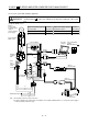
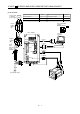
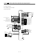
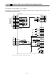
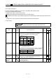
(2) CN1 signal assignment
The signal assignment of connector changes with the control mode as indicated below;
For the pins which are given parameter No.s in the related parameter column, their signals can be
changed using those parameters.
(Note2)
I/O Signals in control modes
Connector Pin No.
(Note1)
I/O
SS/TT
Related
parameter
1 VIN VIN VIN
2 I TLA TLA/TC TC
3 I ST1 ST1/RS2 RS2 No.43 to 48
4 I SON SON SON No.43 to 48
5 I ST2 LOP RS1 No.43 to 48
6I LSP LSP/ No.43 48
7I LSN LSN/ No.43 48
8 I EMG EMG EMG
9O ALM ALM ALM No.49
10 O SA SA/ No.49
11 O RD RD RD No.49
12 O ZSP ZSP ZSP No.1, 49
13 SG SG SG
14 LG LG LG
15 O LA LA LA
16 O LAR LAR LAR
17 O LB LB LB
18 O LBR LBR LBR
19 O LZ LZ LZ
20 O LZR LZR LZR
21 O OP OP OP
22
23
24
25
CN1
26 I VC VC/VLA VLA
Note: 1. I : Input signal, O: Output signal
2. S : Speed control mode, T: Torque control mode, S/T: Speed/torque control switching mode