
Instruction manual

15 - 57
15. MR-E-
AG SERVO AMPLIFIER COMPATIBLE WITH ANALOG INPUT
15.5.4 External I/O signal display
The ON/OFF states of the digital I/O signals connected to the servo amplifier can be confirmed.
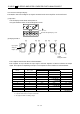
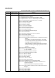
(1) Operation
Call the display screen shown after power-on.
Using the "MODE" button, show the diagnostic screen.
Press UP once.
External I/O signal display screen
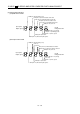
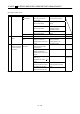
(2) Display definition
CN1
6
CN1
7
CN1
21
CN1
5
CN1
9
CN1
3
CN1
4
CN1
12
CN1
11
CN1
10
Lit: ON
Extinguished: OFF
Input signals
Output signals
CN1
8
Always lit
The 7-segment LED shown above indicates ON/OFF.
Each segment at top indicates the input signal and each segment at bottom indicates the output
signal. The signals corresponding to the pins in the respective control modes are indicated below:
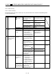
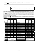
(Note 2) Signal abbreviation
CN1
Pin No.
Input/Output
(Note 1) I/O
ST
Related parameter No.
3 I ST1 RS2 43 to 47
4 I SON SON 43 to 47
5 I ST2 RS1 43 to 47
6 I LSP 43 to 48
7 I LSN 43 to 48
8IEMGEMG
9OALMALM49
10 O SA 49
11 O RD RD 49
12 O ZSP ZSP 49
21 O OP OP
Note: 1. I: Input signal, O: Output signal
2. S: Speed control mode, T: Torque control mode.
3. The signal of CN1A-18 is always output.