SERVO AMPLIFIERS & MOTORS MR-E User-friendly servo with easy operation Mitsubishi Electric Corporation Nagoya Works is a factory certified for ISO14001 (standards for environmental management systems) and ISO9001(standards for quality assurance management systems) EC97J1113
Competent footwork Enhancing 1
created by high performance and easy operations the system cost performance 1. High Performance ●Integrating the MR-J2-Super’s high performance High response is realized. High-accuracy positioning is possible. ● Gain settings can be performed easily by the advanced real-time auto-tuning function. ● Vibration can be suppressed by the adaptive vibration control function. ● Optimum tuning is possible with a personal computer and the setup software.
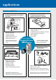
Applications Extensive applications Processing machines or machine tool feed Z Food processing machines, packing machines or feeders X Y Grinding machines Transfer machines Loaders/unloaders Wood working machines Dedicated machines Various positioning can be completed easily with pulse trains.
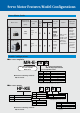
Servo Motor Features/Model Configurations Servo Motor Series Medium capacity series Small capacity series Motor series With Global standards Rated speed Rated output electro(maximum speed) Protection magnetic UL level EN (kW) brake cUL (r/min) (B) Feature ●HF-KE series ● Belt IP65 IP55 3000 (4500) ● Mounters 4 types 0.1, 0.2, 0.4, 0.75 Excluding the shaftthrough portion and connector ● Sewing Stable control from low speeds to high speeds allows compliance with a variety of applications.
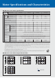
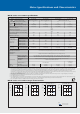
Motor Specifications and Characteristics HF-KE series servo motor specifications Servo motor series HF-KE series (Low inertia, small capacity) Models Servo motor model Specifications Servo amplifier model HF-KE13 (B) HF-KE23 (B) HF-KE43 (B) HF-KE73 (B) MR-E-10A/AG (Note 9) MR-E-20A/AG (Note 9) MR-E-40A/AG (Note 9) MR-E-70A/AG (Note 9) Power facility capacity (Note 2) (kVA) Continuous Rated output (W) running Rated torque (N·m [oz·in]) duty 0.3 0.5 0.9 1.3 100 200 400 750 0.32 (45.3) 0.
Motor Specifications and Characteristics HF-SE series servo motor specifications Servo motor series Models Servo motor model HF-SE series (Medium inertia, medium capacity) HF-SE52 (B) HF-SE102 (B) MR-E-70A/AG (Note 7) MR-E-100A/AG (Note 7) Power facility capacity (Note 1) (kVA) 1.0 1.7 2.5 Continuous running duty 0.5 1.0 1.5 2.0 2.39 (338) 4.77 (675) 7.16 (1010) 9.55 (1350) 7.16 (1010) 14.3 (2020) 21.5 (3040) 28.
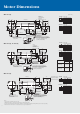
Motor Dimensions ●HF-KE13(B) (Unit: mm) 2-ø4.5 mounting hole Use hexagonal cap head bolts. 20.5 96.4(137.5) 20.7 1 2.5 3 2 M40 25 5 Standard 4 A 45° with Brake Power supply 6 38.8 (Note 3) ø30h7 ø4 37.1 28.5 21 ø8h6 20.7 21.5 (Note 3) 7.2 1 4 2 5 3 6 A 18.4 (Note 3) 25.2 72.3(Note 3) 19.2 Power supply lead 13.9 0.3m 27.5 40.5 Power supply connector pin assignment Pin No. Signal name 1 U phase 2 V phase 3 W phase 4 Earth 6.4 connector pin assignment Pin No.
Motor Dimensions ●HF-SE52(B), HF-SE102(B), HF-SE152(B) (Unit: mm) 4-ø9 mounting hole Use hexagonal cap head bolts. L 39.7(45) 55 50 12 M130 45° 3 (Note 3) ø1 ø1 65 112.5 (Note 3) ø110h7 (Note 3) 81.5 79.9(Note 3) (Note 3) 45 ø24h6 (Note 3) 19.5 (Note 3) (Note 3) 60.5(Note 3) 20.9 Encoder connector MS3102A20-29P 13.
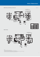
Motor Special Specifications Special shaft end specifications Motors with the following specifications are available. HF-KE series ● With key (200, 400, 750W) R Q Variable dimensions S R Q W QK QL U Y QK 200, 400 5 14h6 30 27 5 20 3 3 M4 screw Depth: 15mm 750 6 19h6 40 37 6 25 5 3.5 M5 screw Depth: 20mm HF-KEMK QL U A øS T W Capacity (W) Motor model (Note 1) Y T A A-A (Unit: mm) ● D-cut (100W) 25 (Note 1) 21.5 1 20.
Peripheral Equipment (standard interface) Connections with peripheral equipment Peripheral equipment is connected to MR-E as described below. Connectors, options, and other necessary equipment are available so that users can set up MR-E easily and begin using it right away. Power supply 3-phase 200-230VAC or 1-phase 230VAC CN3 for RS-232C communication (option) Display panel Displays monitoring data, parameters, and alarms.
Amplifier Specifications MR-E-A Servo amplifier model MR-E- 10A Voltage/frequency (Note 1) Power supply Permissible voltage fluctuation 20A 40A 70A 3-phase 200 to 230VAC: 3-phase170 to 253VAC 1-phase 230VAC: 1-phase207 to 253VAC 3-phase 170 to 253VAC ±5% maximum Permissible frequency fluctuation Sine-wave PWM control/current control system Dynamic brake Safety features Built-in None None Installed Installed Installed Installed Overcurrent shutdown, regeneration overvoltage shutdown, overload s
Standard Wiring Diagram MR-E-A type: Position control operation ●Connection to QD75D (position servo, incremental) Create a sequence that cuts off the MC when an alarm or emergency stop occurs. NFB MC Power supply 3-phase 200 to 230VAC or 1-phase 230VAC (Note 12) Servo amplifier MR-E-MA CNP 1 CNP 2 U L1 L2 L3 Servo motor HF-KE series U 1 V 2 W V W 4 The servo amplifier could be damaged if the optional regeneration unit is incorrectly connected.
Standard Wiring Diagram MR-E-A type: Internal speed control operation ●Connection Create a sequence that cuts off the MC when an alarm or emergency stop occurs.
Standard Wiring Diagram MR-E-AG type: Speed control operation ●Connection Create a sequence that cuts off the MC when an alarm or emergency stop occurs.
Standard Wiring Diagram MR-E-AG type: Torque control operation ●Connection Create a sequence that cuts off the MC when an alarm or emergency stop occurs.
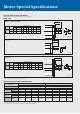
Amplifier Dimensions ●MR-E-10A/AG, 20A/AG (Unit: mm) Approx. 70 50 135 Space required for heat radiation (40 minimum) 6 156 6 168 6 ø6 mounting hole Space required for heat radiation (40 minimum) 6 Three ground (PE) terminals (M4) Mounting screw size: M5 4 ●MR-E-40A/AG 70 22 135 156 6 168 Approx.
Amplifier Dimensions ●MR-E-70A/AG, 100A/AG (Unit: mm) Approx. 70 190 70 22 25 Space required for heat radiation (40 minimum) 168 156 ø6 mounting hole 6 Space required for heat radiation (40 minimum) 22 42 6 6 Three ground (PE) terminals (M4) Mounting screw size: M5 ●MR-E-200A/AG Approx.
Options ● Optional regeneration unit Built-in regenerative resistor/tolerable regenerative power (W) MR-RB032 MR-RB12 MR-RB30 MR-RB32 MR-RB50 Resistance value (Ω) MR-E-10A/AG — 30 ✕ ✕ ✕ ✕ 40 MR-E-20A/AG — 30 100 ✕ ✕ ✕ 40 MR-E-40A/AG 10 30 100 ✕ ✕ ✕ 40 MR-E-70A/AG 20 30 100 ✕ 300 ✕ 40 MR-E-100A/AG 20 30 100 ✕ 300 ✕ 40 MR-E-200A/AG 100 ✕ ✕ 300 ✕ 500 13 Servo amplifier model Optional regeneration unit/tolerable regenerative power (W) Notes: 1.
Options ● Cables and connectors (for MR-E-MA/AG type) Optional cables and connectors are shown in the diagram below.
Options Item For CN3 i o For brake Select one for use with motor power supply (for CNP2) Select one for use with amplifier power supply (for CNP1) Select one for use with motor power supply (motor side) !0 Personal computer communication cable Analog monitor RS-232C connector Analog monitor/RS-232C branch cable Model QC30R2 Cable length 3m MR-ECN3 (20 pcs/box unit) MR-E3CBL15-P Protection level — — Description RS-232C option connector (Marushin electric mfg.
Ordering Information for Customers Ordering information for customers 2 1 Plug Cable clamp 2 Cable 1 Plug Cable clamp Cable ● Servo motor power supply connectors Power supply connectors are not included with the motors. Order from the previous pages, or choose from among the following recommended products. To order the following recommended products, contact the relevant manufacturers directly.
Ordering Information for Customers/Options ● Brake connectors Brake connectors are not included with the motors. Order from the previous pages, or choose from among the following recommended products. To order the following recommended products, contact the relevant manufacturer directly.
Peripheral Equipment ● EMC filter The following filters are recommended as a filter compliant with the EMC directive for the servo amplifier’s power supply. Model Applicable servo amplifier Fig. SF1252 MR-E-10A/AG to MR-E-100A/AG A SF1253 MR-E-200A/AG B External dimensions ● SF1252 Connections (Unit: mm) 149.5 ø6.0 156.0 168.0 140.0 LINE (input side) A LOAD (output side) 8.5 16.0 42.0 Servo amplifier EMC filter Model Mass kg (lb) SF1252 0.75 (3.
Peripheral Equipment ● Electrical wires, circuit breakers and magnetic contactors Electrical wire size (mm2) (Note 1) Circuit breaker Magnetic contactor 30A frame 5A S-N10 2 (AWG14) 1.25 (AWG16) 2 (AWG14) 1.25 (AWG16) MR-E-20A/AG 30A frame 5A S-N10 2 (AWG14) 1.25 (AWG16) 2 (AWG14) 1.25 (AWG16) MR-E-40A/AG 30A frame 10A S-N10 2 (AWG14) 1.25 (AWG16) 2 (AWG14) 1.25 (AWG16) MR-E-70A/AG 30A frame 15A S-N10 2 (AWG14) 1.25 (AWG16) 2 (AWG14) 1.
Using a Personal Computer Software to facilitate a use with a personal computer is available. ● MRZJW3-MOTSZ111E A user-friendly design facilitates selecting the optimum servo amplifier, servo motor (including the servo motor with a electromagnetic brake) and optional regeneration unit just by entering constants and an operation pattern into machine-specific windows. Features (1) User-defined operation patterns can be set.
Using a Personal Computer < Setup software > ● MRZJW3-SETUP154E (Note6) (E:English) This software makes it easy to perform monitor display, diagnostic, reading and writing of parameters, and test operations from the setup with a personal computer. ● Operating conditions Features (1) This software can easily set up and tune your servo system with a personal computer. Compatible personal computers: Windows® 95, Windows® 98, Windows® 98 Second Edition, Windows® Me, Windows NT® Workstation4.
The Differences: Comparison with MR-J2-Super Series The Differences (Comparison with MR-J2-Super series) ● Servo amplifier MR-E-MA/AG series Item External dimensions/Mounting method MR-E-MA/AG MR-J2S-MA Same as MR-J2-MA — External connection Rated output Encoder 0.1 to 2kW 0.
Cautions Concerning Use To ensure safe use • To use the products given in this catalog properly, always read the “Installation Guide” and “MR-J3 INSTRUCTION MANUAL” before starting to use them. • These products have been manufactured as a generalpurpose part for general industries, and have not been designed or manufactured to be incorporated in a device or system used in purposes related to human life.
Cautions Concerning Use Operation • When a magnetic contactor (MC) is installed on the amplifier’s primary side, do not perform frequent starts and stops with the MC. Doing so could cause the amplifier to fail. • Turn MC OFF if an alarm occurs. • As for the amplifier, when a trouble occurs, the amplifier’s safety features are activated, halting output, and the dynamic brake instantly stops the motor. • When using a motor with an electromagnetic brake, do not apply the brake when the servo is on.
MEMO 30
Safety Warning To ensure proper use of the products listed in this catalog, please be sure to read the instruction manual prior to use. L(NA)03018A 0507 Printed in Japan (MDOC) New publication, effective July 2005 Specifications subject to change without notice.