
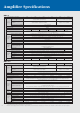
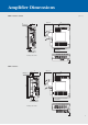
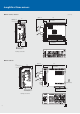
Specifications


12
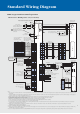
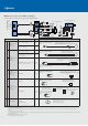
Standard Wiring Diagram
Notes:
1. Do not reverse the diode’s direction. Connecting it backwards could cause the servo amplifier to malfunction that signals are not output, and emergency stop and other safety circuits are
inoperable.
2. Provide a 24VDC ±10% 200mA power supply from an external source for the interface. 200mA is the value when all input/output signals are used. The current capacity can be stepped
down according to the number of input/output points in use.
3. EMG (emergency stop) contact (normally closed contact) must be installed. If it is not installed, operation will be impossible.
4. LSP and LSN contacts must be closed for normal operation. If they are not closed, the commands will not be accepted.
5. Signals with the same name are connected inside.
6. Malfunction signal (ALM) is turned on during normal operation when no alarms have been triggered.
7. For the motor with an electromagnetic brake. The electromagnetic brake terminals (B1, B2) do not have the polarity.
8. Connect the shield wire securely to the plate inside the connector (ground plate).
9. This connection is not necessary for QD75D of the positioning unit. Note that the connection between LG and control common terminal is recommended to increase noise resistance
depending on the positioning unit being used.
10. Always use a shielded multicore cable up to a maximum of 15m in a low noise environment. However, if the RS-232C communication is set up with a baud rate of more than
38400bps, keep the cable length to within 3m.
11. Refer to “MR-E-A/AG INSTRUCTION MANUAL” for details.
12. When using a 1-phase 230VAC power supply, connect the power supply to the L1 and L2 terminals. Do not connect anything to L3. The 1-phase 230VAC power supply is available only
for MR-E-70A or smaller servo amplifiers.
13. Use the analog monitor/RS-232C branch cable (MR-E3CBL15-P) when connecting the analog monitor output 1 (MO1), analog monitor output 2 (MO2) and a personal computer.
Create a sequence that cuts off the MC
when an alarm or emergency stop occurs.
Servo amplifier
MR-E-MA
(Note 11)
B1
B2
SM
Electromagnetic
brake
(Note 7)
7P5
8LG
1MR
2
MRR
4MD
5
MDR
3—
9SD
6 CNT
7P5
8LG
1MR
2
MRR
4MD
5
MDR
3—
9SD
6 CNT
RS-232C
RD
GND
GND
SD
(Note 10)
15m maximum
Personal computer
running
Microsoft Windows
Maximum +1mA total
Double oscillation (±10V output)
Monitor output
Monitor output 1
Monitor output 2
10kΩ
10kΩ
2m maximum
U
V
W
1P5
2LG
3MR
4
MRR
7MD
8
MDR
9—
10 LG
PLATE
SD
SM
A
U
V
W
B
C
D
B1
B2
CN2
(Note 11)
S
R
C
D
A
B
F
G
N
M
Electromagnetic
brake
(Note 7)
(Note 13)
1P5
2LG
3MR
4 MRR
7MD
8 MDR
9—
10
LG
SD
PLATE
Servo motor
HF-SE series
Servo motor
HF-KE series
U
V
W
P
C
L1
L2
L3
U
V
W
D
Encoder
Encoder
NFB
MC
Power supply
3-phase 200 to 230VAC
or
1-phase 230VAC (Note 12)
Optional
regeneration unit
CNP 1 CNP 2
Positioning unit QD75D
PULSE F+
MM15
MM16
MM 9
MM10
MM12
MM14
MM11
MM18
MM13
MM17
Name
Pin No.
PULSE F–
PULSE R–
CLEAR
CLEAR COM
RDY COM
PG05
PG0 COM
READY
PULSE R+
PP
23
PG
22
NP
25
NG
24
CR
5
SG
13
RD
11
LZ
19
LZR
20
LG
14
LA
15
LAR
16
LB
17
LBR
18
LG
14
OP
21
SD
PLATE
(Note 3) Emergency stop
Servo on
Reset
Forward stroke end
Reverse stroke end
External 24VDC
power supply
(0.2A or more)
(Note 4)
(Note 6)
Malfunction
Zero speed detection
In position
(Note 1)
10m maximum
10m maximum
EMG
SON
RES
LSP
LSN
SG
ZSP
ALM
8
4
3
6
7
13
12
9
INP
10
OPC
VIN
2
1
MO14
A
A
MO2
6
LG
3
SD
PLATE
TXD2
LG3
R
XD1
CN3
CN2
Shut off when the servo
on signal turns off and
when alarm signal is issued.
EMG
Power supply 24VDC for
the electromagnetic brake
1
2
3
4
5
6
(Note 9) Control common
Encoder A-phase pulse
(differential line driver)
Encoder B-phase pulse
(differential line driver)
Encoder Z-phase pulse
Control common
Control common
CN1
(Note 5)
RA1
RA2
RA3
10m maximum
for differential line driver.
2m maximum
for open collector.
(open collector)
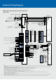
MR-E-A type: Position control operation
●Connection to QD75D (position servo, incremental)
The servo amplifier could be
damaged if the optional
regeneration unit is incorrectly
connected.
Disconnect P and D
when connecting the
optional regeneration
unit externally.
Connect P and D when
using the built-in
regenerative resistor.
(Note 2)
Built-in
regenerative
resistor
EMG
Shut off when
the servo on
signal turns off
and when alarm
signal is issued.
24VDC